In the industrial world, equipment often needs to be tailored to meet unique process requirements. This frequently leads to non-standard designs that fall outside the guidelines of recognized standards like ASME. While these standards provide excellent protocols for standard designs, they rarely address the complexities of bespoke equipment.
When faced with such challenges, engineers must turn to innovative solutions like Finite Element Analysis (FEA) to validate and optimize these non-standard designs. Let’s explore how FEA can help transform unconventional concepts into reliable, efficient, and safe solutions.
Problem Statement
Our client was tasked with designing a foam separator for alcohol processing—a vertical vessel shell equipped with a centrifuge duct nozzle. Since the design was non-standard, specific ASME guidelines were unavailable. Initially, the separator was designed based on general engineering principles, but modifications were needed to ensure the design met FEA safety criteria.
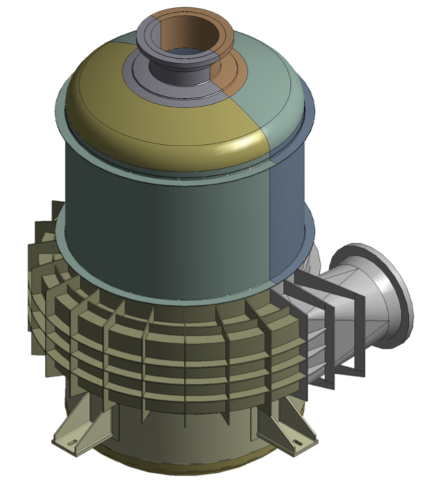
Fig – Foam separator.
Challenges
Creating a foam separator with non-standard specifications posed several challenges:
- No clear guidelines: ASME standards didn’t cover the unique aspects of the design.
- Complex geometry: The design featured intricate components like nozzles, ducts, and dish ends.
- Stress optimization: Ensuring the vessel could handle various loads without exceeding allowable stress limits.
Manual calculations for thickness and stress distribution were impractical, requiring a systematic approach involving 3D modeling and FEA.
Solution
Initial Design and FEA
A 3D CAD model of the foam separator was created using the client’s geometric specifications. The model included critical components such as the shell, top dish end, bottom dish end, nozzles, and ducts.
Primary Design Considerations:
- Shell thickness: 6 mm
- Bottom dish end thickness: 8 mm
- Duct top, bottom, and side plate thickness: 6 mm
First FEA Iteration Results:
The initial FEA revealed stress concentrations exceeding allowable limits, signaling potential design failure.
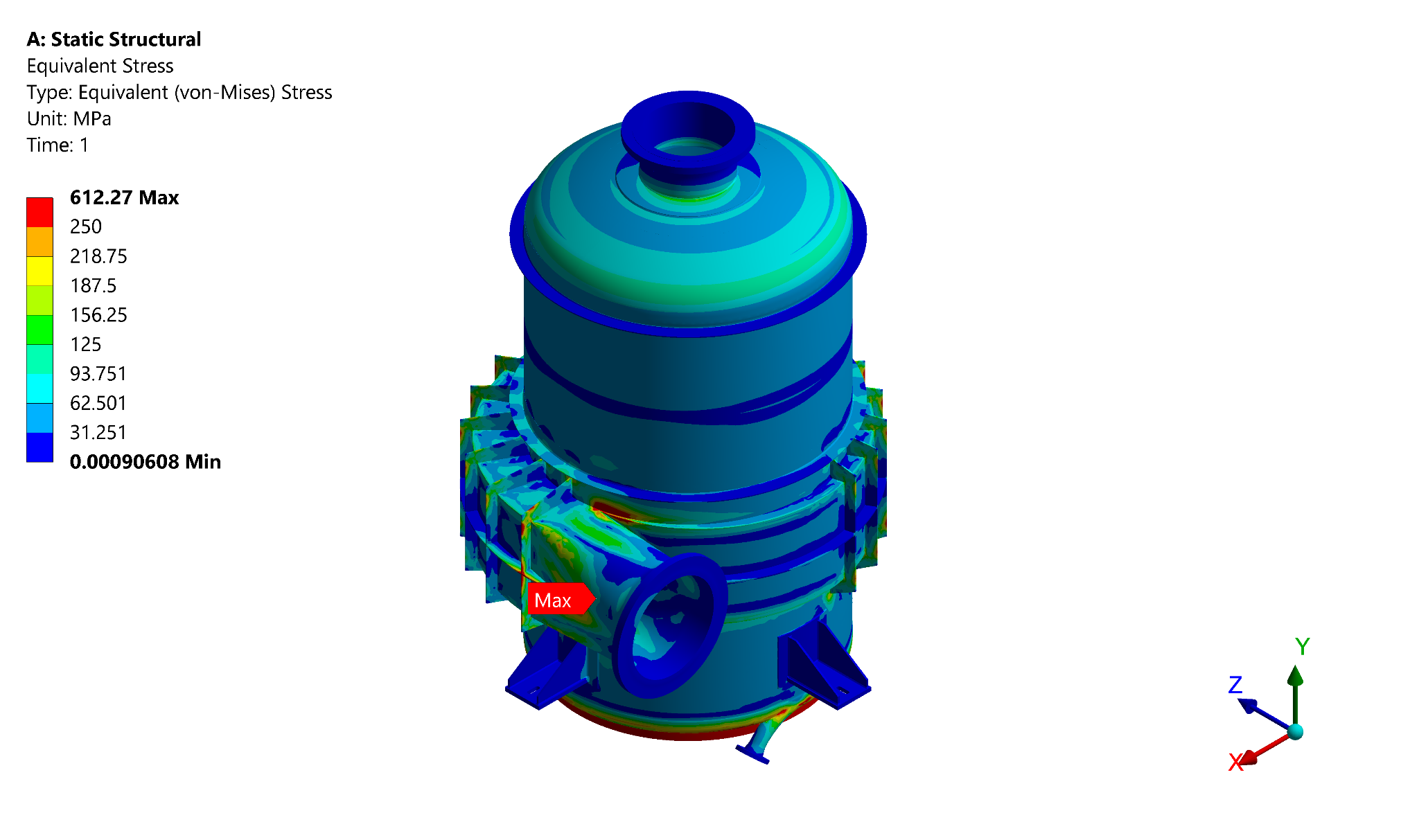
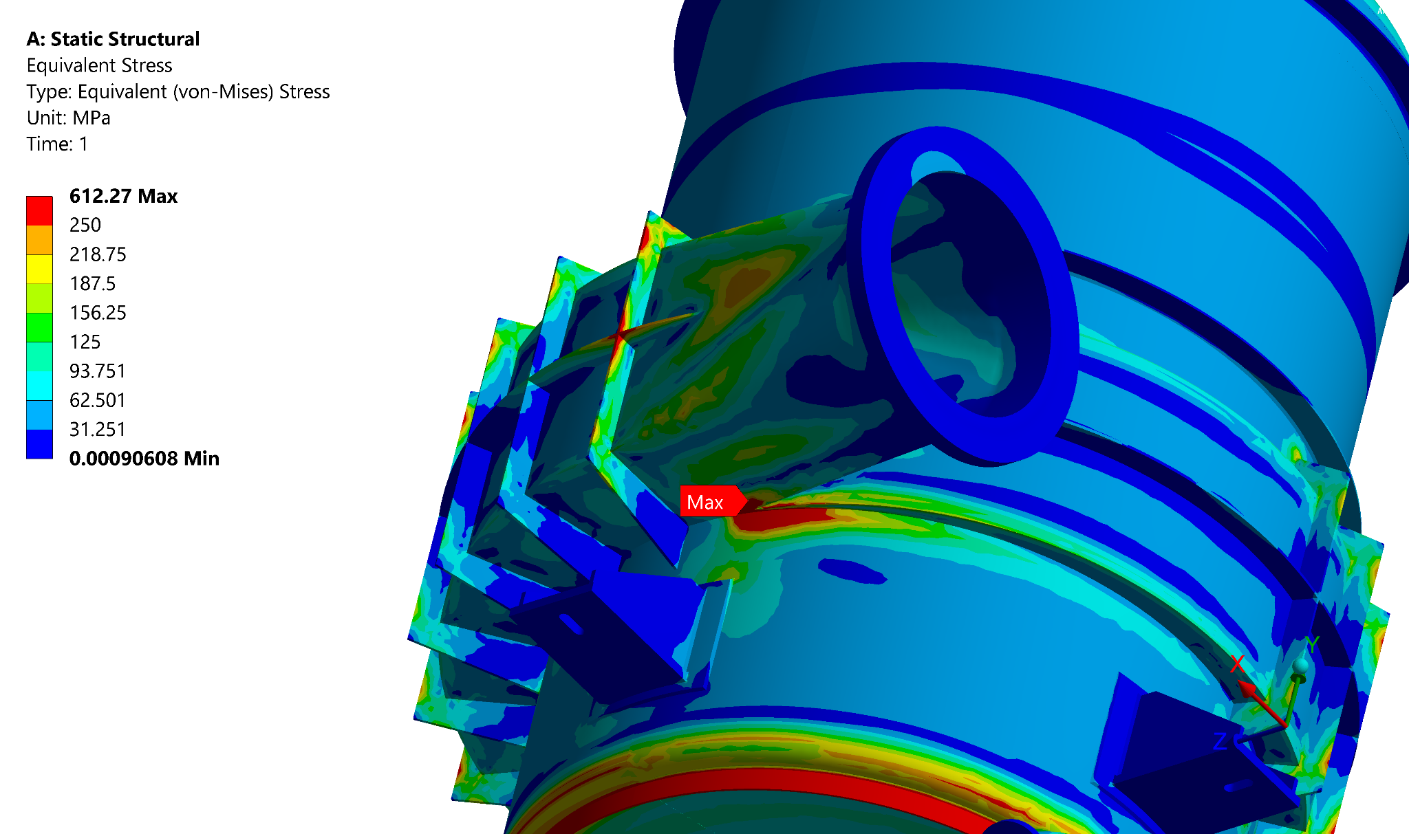
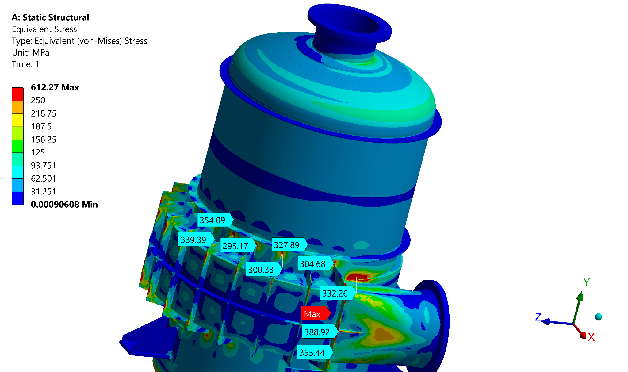
Fig – Stresses induced in primary FEA iteration
Geometric Modifications
To address these issues, several design changes were implemented:
- Increased Thicknesses:
- Shell: 6 mm → 8 mm
- Bottom dish end: 8 mm → 12 mm
- Duct plates: 6 mm → 8 mm
- Added Stiffeners:
- Four 8 mm thick stiffeners were added to the duct.
- An L-angle stiffener and an additional stiffener were added to the bottom dish end.
- Enhanced Structural Support:
- The RF pad at the stiffener-to-shell junction was replaced with a complete shell pad plate.
- Two gussets were added for nozzle B01.
These updates were incorporated into a revised 3D CAD model, which was then subjected to a second round of FEA.
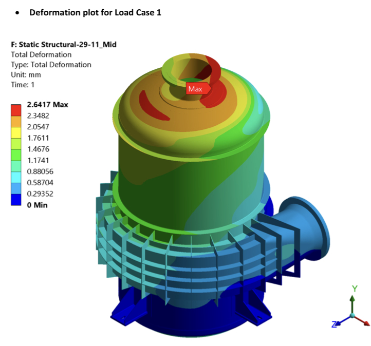
Fig – deformation plot for load case
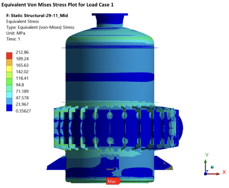
Fig – equivalent stress plot for load case
Updated Design Analysis
The updated design was analyzed under the following load conditions:
- Self-weight: Acting downward on the vessel.
- Internal Design Pressure: 0.3 MPa.
- External Pressure: Applied by the connected pipe on the vessel wall.
Key Results:
- Deformation Plot: Maximum deformation occurred on the upper side at nozzle B02.
- Equivalent Stress Plot: The maximum von Mises stress was 212.86 MPa, observed at the bottom dish side of the vessel.
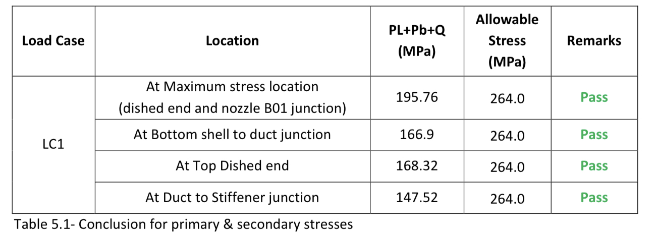
The critical stress points were found at:
- The bottom shell-to-RF pad junction.
- The top dish end.
- The duct-to-stiffener junction.
Stress Range:
- Primary and secondary stresses ranged from 147.52 MPa to 195.76 MPa, well below the allowable stress limit of 264 MPa, confirming the design’s safety.
Conclusion
Designing non-standard industrial equipment requires creative problem-solving and rigorous validation. In the case of the foam separator, FEA allowed us to analyze, modify, and optimize the design, ensuring it met safety and performance standards even in the absence of specific ASME guidelines.
This approach highlights the power of FEA in:
- Validating unconventional designs.
- Ensuring reliability and safety.
- Enhancing operational efficiency and productivity.
By bridging the gap between innovation and standardization, FEA empowers industries to tackle unique challenges while delivering high-quality solutions tailored to their needs.