
When a pressure vessel leaks, a pump shaft snaps, or a pipeline ruptures, the incident rarely comes out of nowhere. Equipment failures almost always develop over time beginning with a microscopic crack or localized damage that, under the right conditions, grows until the structure can no longer carry its load. Understanding that sequence is the foundation of engineering failure analysis.
Failure mechanism analysis is the discipline engineers use to identify and explain the specific physical process that caused a component to degrade and eventually fail. Whether the failure occurred in an oil and gas pipeline, a power plant boiler, a chemical process vessel, or a critical rotating machine, the methodology is the same: trace the evidence backward from the final fracture surface to the very first signs of damage.
This article walks through how engineers conduct that investigation from the stages of mechanical failure and the most common damage mechanisms to the tools and techniques used to build a defensible, technically rigorous conclusion.
What Is Failure Mechanism Analysis?
Failure mechanism analysis is the systematic process of identifying the physical or chemical process by which a component or structure degraded and lost its ability to perform its intended function. Common mechanisms include fatigue cracking, corrosion, creep rupture, and brittle fracture.
Every failure has a mechanism, the underlying physical process that drove the damage. Engineers must identify this mechanism before any meaningful corrective action can be recommended. Without it, repairs address symptoms rather than causes.
The mechanism is not the same as the root cause. Fatigue cracking is a mechanism. The root cause might be an undersized fillet radius, a misaligned bearing, or an incorrect operating frequency. Understanding the mechanism is the essential first step toward identifying that deeper cause.
| Damage Mechanism | Typical Industry Example |
|---|---|
| Fatigue cracking | Rotating shafts in compressors and pumps |
| Stress corrosion cracking | Stainless steel process piping in chloride environments |
| Creep rupture | Superheater tubes in high-temperature boilers |
| Brittle fracture | Pressure vessels operating below ductile-to-brittle transition temperature |
| Hydrogen embrittlement | High-strength steel fasteners in refinery environments |
| Corrosion thinning | Carbon steel pipelines carrying wet sour service fluids |
What Is Engineering Failure Analysis?
Engineering failure analysis is a structured, evidence-based investigation that determines why a component, structure, or system failed. It combines physical examination, metallurgical testing, fracture mechanics assessment, and operating history review to produce a technically defensible explanation of the failure.
Basic troubleshooting asks: what broke and what do we replace? Engineering failure analysis asks something far more rigorous: why did this part fail here, at this time, in this manner? The distinction matters enormously in safety-critical industries where recurring failures carry serious consequences.
A thorough engineering failure analysis typically includes:
- Failure investigation: Documenting the failure event, gathering witness statements, and preserving physical evidence before it is disturbed or cleaned.
- Metallurgical examination: Analysing the material’s microstructure, composition, hardness, and fracture surface to characterize the failure mode.
- Fracture mechanics assessment: Applying quantitative methods to determine whether the observed crack size and loading conditions are consistent with the proposed failure scenario.
- Operating history review: Examining maintenance records, process data, inspection reports, and any recent changes to operating conditions.
Why Equipment Failures Must Be Investigated Systematically
A common mistake in industry is assuming the cause of a failure based on past experience alone. Two failures that look identical on the surface can have entirely different root causes. A shaft that broke at the same location as a previous failure might have fractured by fatigue on the first occasion and by torsional overload on the second. Treating them the same way leads to a repeat failure.
Root cause failure analysis in engineering provides the framework that prevents this error. By requiring physical evidence to support every conclusion, it removes assumptions from the investigation process. The benefits extend beyond simply fixing the immediate problem:
- Prevent recurrence: Corrective actions target the actual cause, not a symptom.
- Improve reliability: Understanding failure patterns helps engineers design out vulnerabilities.
- Maintain safety: Identifying failure mechanisms before catastrophic failure allows controlled corrective action.
- Support regulatory compliance: Many industries require documented failure investigations for safety case management and insurance purposes.
- Improve equipment design: Findings feed back into engineering standards and design specifications.
Stages of Mechanical Failure
Most structural and mechanical failures develop through three well-defined stages. Recognizing these stages on the fracture surface is one of the most powerful tools an engineer has for understanding what happened.
1. Crack Initiation
Crack initiation is the starting point of failure. A crack does not form in an undamaged, uniformly stressed material without a reason. Initiation almost always occurs at a point of stress concentration a geometric feature, surface defect, or microstructural discontinuity that causes the local stress to significantly exceed the nominal stress in the component.
Common initiation sites include:
- Stress concentrations at notches, keyways, sharp corners, and thread roots.
- Manufacturing defects such as porosity, inclusions, or machining marks.
- Corrosion pits that act as localized stress risers on an otherwise smooth surface.
- Microstructural defects introduced during welding, heat treatment, or forming.
In fatigue failure, the initiation stage may consume the majority of the component’s total life. A crack can remain small enough to be undetectable for thousands or even millions of load cycles before it begins to propagate measurably.
2. Crack Propagation
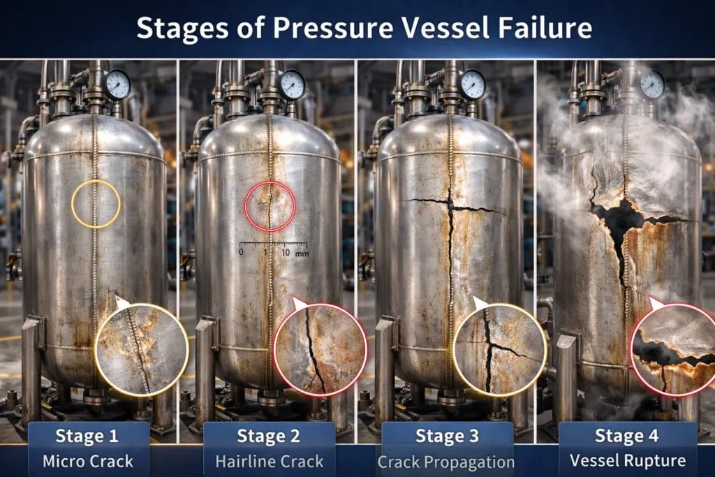
Once a crack has initiated, each load cycle causes it to advance by a small increment often measured in nanometers or micrometers per cycle. This is the crack propagation stage, and it is governed by the principles of fracture mechanics.
The key parameter in fracture mechanics is the stress intensity factor (K), which describes the magnitude of the stress field at the crack tip. As the crack grows longer, K increases for the same applied load. When K exceeds the material’s fracture toughness (K_IC), rapid, unstable fracture occurs.
On a fracture surface, fatigue crack propagation leaves behind characteristic beach marks curved, concentric lines that show the successive positions of the crack front as it advanced. These markings allow engineers to reconstruct the crack’s growth history and estimate how long propagation continued before final rupture.
3. Final Rupture
Final rupture occurs when the remaining uncracked cross-section can no longer support the applied load. The transition from stable crack propagation to catastrophic fracture happens rapidly often in fractions of a second.
The character of final rupture depends on the material and temperature. Ductile rupture is characterized by significant plastic deformation before fracture, a rough, fibrous fracture surface, and a reduction in cross-sectional area at the fracture location. Brittle fracture, by contrast, involves little or no plastic deformation, a flat, crystalline fracture surface, and often a chevron pattern pointing back toward the initiation site.
The ratio of the crack propagation zone to the final fracture zone on a fracture surface provides information about the relative magnitude of the applied load. A small final fracture zone indicates that the component was lightly loaded; a large final fracture zone suggests high applied loads or sudden overload.
Common Failure Mechanisms Engineers Identify
| Failure Mechanism | Description | Typical Equipment |
|---|---|---|
| Fatigue failure | Progressive crack growth driven by cyclic loading, often with no visible warning before final fracture. | Rotating shafts, pressure vessel nozzles, pipeline welds |
| Stress corrosion cracking (SCC) | Simultaneous effect of tensile stress and a corrosive environment producing cracks in susceptible materials. | Stainless steel and high-strength alloy components in chloride or H₂S environments |
| Creep rupture | Time-dependent plastic deformation and eventual fracture at elevated temperatures under sustained stress. | Boiler tubes, turbine blades, high-temperature piping |
| Brittle fracture | Sudden, low-energy fracture with minimal plastic deformation, often triggered by low temperature or high loading rate. | Pressure vessels, storage tanks, structural welds |
| Hydrogen embrittlement | Absorption of atomic hydrogen reduces ductility and fracture toughness, causing premature cracking. | High-strength fasteners, welds in wet sour service, electroplated components |
| Corrosion thinning | General or localized metal loss due to chemical or electrochemical attack, reducing load-carrying capacity. | Pipelines, heat exchangers, storage vessels in corrosive service |
How Engineers Perform Failure Mechanism Analysis
Equipment failure analysis and structural failure analysis follow a consistent methodology regardless of the industry or equipment type. The investigation proceeds as follows:
- Equipment inspection: Engineers document the as-found condition of the failed component, including location, orientation, and any secondary damage. Photographs are taken before any cleaning or sectioning. Failure to preserve the as-found condition is one of the most common investigation errors.
- Failure surface examination: The fracture surface is examined visually and under low magnification. Engineers look for crack initiation sites, propagation markings such as beach marks or ratchet marks, and the character of the final fracture zone.
- Metallurgical testing: Samples are prepared for laboratory analysis. This may include hardness testing, chemical composition analysis, tensile and impact testing, and microstructural examination via optical microscopy or scanning electron microscopy.
- Load and operating condition review: Engineers review process data, maintenance histories, inspection records, and any reported changes to operating conditions in the period before failure. Anomalies such as overpressure events, abnormal temperatures, or unusual vibration are flagged for correlation with the physical evidence.
- Fracture mechanics assessment: Where appropriate, engineers apply quantitative fracture mechanics to verify that the observed crack dimensions and operating loads are consistent with the proposed failure mechanism. This step helps establish whether a design deficiency contributed to the failure.
- Root cause identification: After establishing the failure mechanism, engineers work backward to identify the underlying cause the condition or decision that allowed the mechanism to develop. This is the focus of root cause failure analysis in engineering.
Tools Used in Engineering Failure Analysis
Modern engineering failure analysis draws on a range of specialized analytical tools. Fracture failure analysis in particular relies on techniques that can reveal information invisible to the naked eye:
- Fractography: The study and interpretation of fracture surfaces. Fractographic analysis identifies the crack initiation site, characterizes the propagation mechanism, and locates the final fracture zone. It is the primary diagnostic tool in any fracture failure analysis.
- Metallography: Preparation and microscopic examination of polished and etched cross-sections through the failed component. Metallography reveals the material’s microstructure, heat treatment condition, weld quality, and the presence of microstructural damage such as creep voids or corrosion products.
- Scanning Electron Microscopy (SEM): High-resolution imaging of fracture surfaces at magnifications far beyond optical microscopy. SEM can identify fatigue striations, intergranular cracking, corrosion products, and other microscale features that confirm the failure mechanism.
- Finite Element Analysis (FEA): Computational modeling of stress and strain distributions in the component under its operating loads. FEA is particularly valuable for identifying stress concentrations that contributed to crack initiation.
- Stress calculations: Hand calculations and code-based methods verify whether the component was adequately designed for its applied loads and confirm whether operating conditions were within design limits.
Example: Failure Analysis of a Pressure Vessel Crack
A process plant reported a through-wall crack discovered during routine inspection of a carbon steel pressure vessel operating in wet gas service. The crack was located at the toe of a nozzle attachment weld a common stress concentration site in pressure vessel design.
The engineering failure analysis proceeded through the following steps:
- Visual examination confirmed that the crack ran circumferentially around the nozzle, consistent with hoop stress loading. Beach marks were visible on the fracture surface under low magnification, indicating fatigue crack propagation.
- Fractographic examination under SEM identified the crack initiation site at the weld toe, where lack of fusion in the original weld had left a sharp pre-existing defect. This defect acted as a stress concentrator, reducing the fatigue initiation life to near zero.
- Metallurgical testing confirmed that the base material and weld metal met the specified composition and hardness requirements. The failure was not attributed to material deficiency.
- Operating history review revealed that the nozzle piping had been subject to mechanical vibration from an inadequately supported adjacent pump for approximately 18 months before the crack was discovered. Vibration measurements confirmed cyclic stresses at the nozzle significantly above the original design basis.
- Fracture mechanics assessment confirmed that the pre-existing weld defect, combined with the elevated cyclic stresses from vibration, was sufficient to initiate and propagate the observed crack to the detected size within the 18-month timeframe.
The root cause failure analysis in engineering concluded that the primary root cause was inadequate pipe support design, which allowed vibration-induced stresses to exceed the fatigue capacity of the welded nozzle connection. A secondary contributory cause was the initial weld defect, which reduced the fatigue initiation threshold.
Difference Between Failure Mechanism and Root Cause
One of the most important distinctions in any failure investigation is the difference between the failure mechanism what happened physically and the root cause why the conditions that allowed the mechanism to develop existed in the first place. Corrective actions must address the root cause, not just the mechanism.
| Failure Mechanism (What Happened) | Root Cause (Why It Happened) |
|---|---|
| Fatigue cracking | Excessive vibration from inadequate pipe support or resonance with operating frequency |
| Stress corrosion cracking | Poor material selection for the service environment or incorrect chemical dosing |
| Creep rupture | Sustained operation above design temperature due to control system failure or incorrect set point |
| Brittle fracture | Operation below minimum design metal temperature or use of non-impact-tested material |
| Hydrogen embrittlement | Inadequate post-weld heat treatment or exposure to unanticipated sour conditions |
| Corrosion thinning | Inspection interval too long, inhibitor underdosing, or material specification error |
Root cause failure analysis in engineering requires engineers to keep asking ‘why’ until they reach a cause that, if corrected, would prevent recurrence. Stopping at the mechanism produces a narrower corrective action that may not address the underlying system or design deficiency.
Why Failure Mechanism Analysis Is Critical for Industrial Safety
The consequences of an unresolved failure mechanism in a safety-critical system can be severe. In pressure equipment, rotating machinery, and structural components, failure without adequate prior investigation and corrective action can lead to:
- Unplanned plant shutdown and the associated production loss, which in large process facilities can reach millions of dollars per day.
- Serious safety hazards including toxic releases, fires, explosions, and structural collapse particularly where failure occurs in pressurized or high-energy systems.
- Significant financial losses from equipment replacement, emergency repair, regulatory penalties, and insurance claims.
Structural failure analysis and material failure analysis are not optional in industries regulated under pressure equipment integrity management standards, pipeline integrity programs, or safety case frameworks. Regulators require documented evidence that failures have been properly investigated and that corrective actions are proportionate to the identified root cause.
Beyond compliance, thorough failure investigation generates institutional knowledge. Organizations that investigate every significant failure systematically build a library of damage mechanism data specific to their equipment and process conditions. Over time, this data drives improvements to inspection intervals, material selection, and design standards that genuinely improve reliability.
Conclusion
Every equipment failure tells a story. It begins at a crack initiation site a stress concentration, a weld defect, a corrosion pit and develops through a propagation phase governed by the applied loads and the material’s resistance to crack growth. It ends with a final rupture when the remaining cross-section is no longer sufficient to carry the load. Failure mechanism analysis gives engineers the tools to read that story from the physical evidence.
Engineering failure analysis is not forensic detective work for its own sake. It is a disciplined, evidence-based process that produces actionable findings: corrective actions grounded in the actual cause of failure, not in assumption or tradition. When conducted rigorously, it prevents recurrence, improves equipment reliability, and protects the safety of people and plant.
The most effective industrial organizations do not wait for failures to investigate. They apply the same analytical thinking proactively reviewing damage mechanism data, performing fitness-for-service assessments, and using inspection findings to identify components approaching the end of their safe operating life. Failure mechanism analysis, in this sense, is as much a tool of reliability engineering as it is of incident investigation.
Written By

PANDHARINATH SANAP
CEO and Co-Founder | IntPE
Pandharinath Sanap is the CEO and Co-Founder of Ideametrics, with more than 15 years of experience in mechanical engineering, engineering assessments, and technical reviews across industrial projects. He is an International Professional Engineer (IntPE)… Know more