Code-Qualifying a Thin Flexible Tubesheet Inside a Waste Heat Boiler with Integrated Steam Drum
When ASME UHX rules couldn’t validate the geometry, a full Design-by-Analysis under ASME Div 2 Part 5 proved the vessel safe, protecting schedule, avoiding costly redesign, and delivering fabrication-ready compliance.
Problem
A Waste Heat Boiler with integrated steam drum and a thin flexible tubesheet whose geometry falls outside the mandatory UHX closed-form rules of ASME Section VIII Division 1
Action
A 2.43-million-node ANSYS Workbench Design-by-Analysis study per ASME Section VIII Division 2 Part 5 routed through U-2(g) / Appendix 46
Outcome
Every stress check PASS, every linearised category inside its allowable, global equilibrium within 0.51%, the vessel was cleared for fabrication and service.
Executive Summary
The Decision Problem
When YOUR fabricator proposes a thin, flexible tubesheet inside YOUR Waste Heat Boiler, and the ASME VIII-1 UHX tubesheet rules simply don’t cover that geometry, you face three bad options: thicken the tubesheet (adds weight, cost, may break hydraulic/thermal design); reject and re-engineer (months of delay, fresh procurement); or prove it safe by analysis. Only the third option keeps the schedule and the design intent intact.
What We Did
Routed the design through the U-2(g) alternative-rules provision of ASME VIII-1 (with Appendix 46), and qualified the entire vessel, shell, steam drum, downcomers, risers, both tubesheets by explicit Design-by-Analysis per ASME VIII Division 2 Part 5 using a 481,684-element, 2.43-million-node ANSYS Workbench model with coupled thermal-structural loading at the 343.33 °C shell / 232.22 °C tube-side gradient.
Business Outcome
- Thin flexible tubesheet design approved, no costly rebuild, no re-procurement
- Fabrication schedule protected; avoided months of delay from thickening or re-design
- Code-defensible evidence package handed to the reviewer (U-2(g) + Div 2 Part 5)
- Operating envelope proven across design pressure, full-vacuum (FV) and hydrotest cases
Technical Outcome
- Worst PL = 81 % of allowable, all stress checks PASS
- Worst PL+Pb+Q = 67 % of allowable, secondary envelope intact
- Hand-calc hoop stress matched FEA to within 0.01 MPa (85.69 vs 85.69)
- Global equilibrium closed to 0.51 %, model trusted
Why This Is Repeatable for You
1. The Engineering Challenge

Fig 1 · As-designed layout of the Waste Heat Boiler, 3048 mm OD shell + 1100 mm OD steam drum with five downcomer/riser pairs linking drum to shell. The thin flexible tubesheets (21.65 mm) at each end are the geometry ASME VIII-1 UHX cannot qualify.
Dimensioned 3D CAD layout of a Waste Heat Boiler with integrated Steam Drum, 6198 mm overall shell length, 3048 mm OD main shell, 2718 mm OD channel, 1100 mm OD steam drum with five downcomer–riser pairs connecting drum to shell, tubesheets 21.65 mm thick at both ends, flexible thin section details annotated.
Waste Heat Boilers recover process heat at the hottest point of a refinery, petrochemical or fertiliser plant, typically immediately downstream of a reformer, SRU or cracker. The combination here is unusual: an integrated steam drum sitting directly above the main shell, connected by five downcomer/riser forging pairs, with thin flexible tubesheets bolted at both ends of the main shell.
That combination is a code headache. ASME Section VIII Division 1 mandates UHX (closed-form rules) for tubesheet design, but UHX assumes a relatively stiff tubesheet geometry. A thin flexible tubesheet mobilises bending, shear and thermal distortion in a way the closed-form equations simply do not capture. The only code-compliant routes left are U-2(g) alternative design combined with explicit Design-by-Analysis per ASME Section VIII Division 2 Part 5.
2. Why This Vessel Matters
Refinery Hydrogen Plants & SRU
WHBs sit in the hottest loop of a hydrogen plant, sulphur recovery unit or reformer effluent. An unplanned shutdown stops the hydrogen supply to the hydrotreaters, cascading to lost production across the entire refinery.
Ammonia, Methanol & Fertiliser Plants
Secondary reformer WHBs capture syngas heat at 340 °C+ to raise HP steam. Tubesheet failure here is a multi-week outage event; the replacement lead time on a large WHB is often six to twelve months.
Petrochem & Power - Waste Heat Recovery Boilers
Ethylene crackers, glycol plants and cogen trains all depend on WHBs to balance heat and steam economics. Fabrication schedule slips propagate directly to commissioning delay, liquidated damages and late start-up.
3. Detailed View - the Three Rectangular Door Openings
Three regions dominate the stress field: the riser and downcomer nozzle forgings where the steam drum meets the main shell, and the tubesheet edge where flexibility interacts with bolt-load and pressure. We modelled all three at refined mesh density.
")
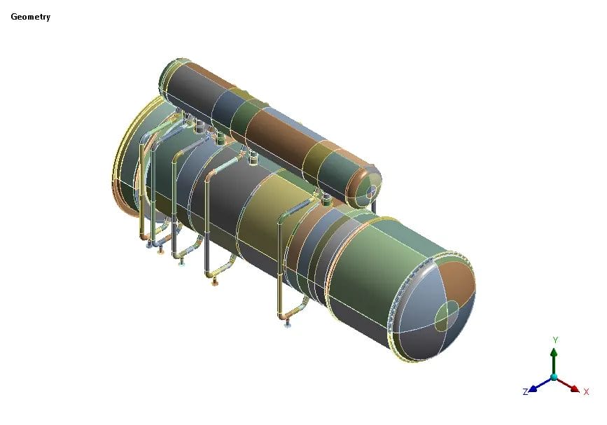
Fig 2 · Assembled 3D FEA geometry, steam drum, main shell, tubesheets, channel sections and all five downcomer/riser nozzle forgings as a single coupled model.
Isometric 3D FEA geometry of Waste Heat Boiler with integrated Steam Drum above, main shell below, five downcomer-riser pairs, dished heads at both ends, channel-side connections, as built for ASME VIII Division 2 Part 5 analysis in ANSYS Workbench.

Fig 3 · Mesh refinement at the riser/downcomer nozzle forging junction – through-thickness resolution engineered to support stress linearisation along the full SCL.
Close-up of SOLID186 / SOLID187 hex-dominant FEA mesh at downcomer nozzle forging to shell junction, showing refined sweep mesh across the fillet weld region and through-thickness resolution for stress linearisation per ASME VIII Division 2 Part 5.

Fig 4 · Temperature field at design condition. The 343.33 – 191.13 °C gradient across the tubesheet is the thermal driver the closed-form UHX rules cannot model.
Steady-state thermal field at Load Case 1 – 343.33 °C maximum on shell and steam drum, 191.13 °C minimum at channel dished head, showing the sharp thermal gradient across the tubesheet and channel that drives differential thermal stress on the thin flexible tubesheet.
4. Codes & Standards - Three Frameworks Stacked
| Framework | Role | What It Gives Us |
|---|---|---|
| ASME VIII Div 1 (2019) + App 46 | Parent code for design | Thickness, materials, allowable, hydrotest basis for the WHB |
| ASME VIII-1 U-2(g) | Alternative-rules provision | Permits Design-by-Analysis when mandatory appendices don’t cover the geometry — the gate we use for the thin flexible tubesheet |
| ASME VIII Div 2 Part 5 (2019) | Design-by-Analysis protocol | Stress categorisation (Pm, PL, PL+Pb+Q), allowable basis (S, Sy, Sps), protection against plastic collapse |
Why the U-2(g) route is defensible?
Appendix 46 of ASME VIII-1 explicitly provides for design validation by analysis when closed-form rules are inadequate. Combining it with Division 2 Part 5 (the canonical DBA protocol) gives a reviewer a complete, code-traceable evidence chain from mandatory parent code, alternative provision, analytical acceptance criteria.
5. Why FEA + FFS Was the Only Defensible Path
- UHX closed-form rules don’t cover thin flexible tubesheets, the geometry sits outside the stiffness assumptions of the appendix.
- The 343 – 232 °C differential is a thermal-structural problem, not a pressure-only one, needs coupled solution.
- Riser / downcomer forging junctions concentrate stress by geometric discontinuity, linearisation along a Stress Classification Line is the only defensible check.
- Full-vacuum (FV) load case flips the pressure sign, closed-form tubesheet rules don’t handle the reversal cleanly.
- Global equilibrium and validation must be documented for the reviewer; closed-form rules give no such audit trail.
- Thermal expansion of 38 mm must be accommodated by the saddle design, only an explicit FEA tells you where and how much.
6. Verdict at Every Critical Location - The Consolidated Table
Every stress check on every critical location, in one scannable view. This is the single table a reviewer (or a plant engineer) wants to see first.
| Check | Load Case | Riser Nozzle Forging | Downcomer Nozzle Forging | Tubesheet LHS | Tubesheet RHS | Allowable | Status |
|---|---|---|---|---|---|---|---|
| PL | LC1 Design |
149.23 | 146.95 | 26.19 | 25.54 | 184.33 / 194.60 | ✓ PASS |
| PL+Pb+Q | LC1 Design |
234.39 | 245.77 | 148.37 | 145.62 | 368.67 / 389.20 | ✓ PASS |
| PL | LC2 FV | 32.53 | — | — | — | 184.33 | ✓ PASS |
| PL+Pb+Q | LC2 FV | 151.30 | — | — | — | 368.67 | ✓ PASS |
| Pm (General membrane — WHB) | LC1 Design |
— | — | 79.02 | — | 129.06 | ✓ PASS |
| Pm (General membrane — Steam Drum) | LC1 Design |
— | — | 63.56 | — | 129.06 | ✓ PASS |
Reading the table:
The riser and downcomer nozzle forgings, not the tubesheets, carry the worst-case stress, running at 80–81 % of the primary-local-membrane allowable. The thin flexible tubesheet itself sits at 13 % of its membrane allowable. The design is not tubesheet-limited; it is nozzle-junction-limited, which is the opposite of what a closed-form UHX analysis would have warned you about.
7. Headline Results
6×
Stress ratio – nozzle forging 81 % vs flexible tubesheet 13 %
81 %
Worst PL utilisation
0.51 %
0.01 MPa

Fig 5 · Total deformation under Load Case 1. The 29.864 mm maximum is thermal growth along the shell axis – it confirms (within 2 %) the hand calculation of 38 mm total expansion across shell + channel and it sets the sliding-saddle travel requirement.
Total deformation plot at Load Case 1 – 29.864 mm maximum displacement at channel dished head, axial growth dominated by thermal expansion of the 6198 mm long shell at 343 °C, confirming the 38 mm total thermal expansion hand calculation to within 2 percent

Fig 6 · Equivalent stress at the riser nozzle forging. 254 MPa peak at the fillet-weld transition – linearised along the SCL, this becomes 149.23 MPa PL and 234.39 MPa PL+Pb+Q, both comfortably inside their allowables.
Close-up equivalent von Mises stress contour at riser nozzle forging to main shell junction at Load Case 1 design pressure plus temperature, showing peak stress of 254.41 MPa at the fillet-weld transition which is then linearised along the Stress Classification Line for code categorisation
8. Lessons Learned - Widely Applicable
1. Thin flexible tubesheets don't fail the code, the code simply doesn't cover them.
Routing through U-2(g) + Div 2 Part 5 is not an exception; it is the designed escape hatch. Use it with confidence when geometry falls outside UHX.
2. Nozzle forgings, not the tubesheet, will drive your worst-case stress.
In this vessel the riser/downcomer junctions sat at 80 % utilisation while the tubesheet itself sat at 13 %. A closed-form UHX check would have looked at the wrong part.
3. Thermal expansion (38 mm here) sets the saddle spec, not the stress rules.
Your sliding-saddle travel and baffle restraints must accept the axial growth FEA predicts or the constraint load will rebuild itself as secondary stress inside the shell.
Request the Complete Technical Report
This PDF case study summaries the stress validation.
- Materials of construction table (SA 516 Gr 70N, SA 350 LF2 Cl 1)
- Mesh sensitivity study (16 mm / 18 mm / 20 mm convergence)
- Full boundary condition set – 12 loading figures
- Individual load-case stress breakdown (LC1 design, LC2 full-vacuum)
- Stress linearisation plots along every SCL
- Primary local membrane (PL) detailed results
- Primary + secondary (PL+Pb+Q) detailed results
- Equivalent stress verdict under FV
- FEA validation – hoop-stress hand calc vs FEA
- Global equilibrium check – applied load vs reaction
- Thermal expansion hand-calc cross-check
- Recommendations for saddle design & sliding-mount travel
- Limitations & assumptions register
Please check your email inbox.