FFS Level 3 Analysis for Shell Dis-Bonding
Contents
- 1. Design Parameters
- 2. Project Overview
- 3. FEA Methodology
- 4. Boundary Conditions & Loading
- 5. Load Case Analysis
- 6. Detailed Results
- 7. Stress Acceptance & Buckling Assessment
- 8. Model Validation
- 9. Lessons Learned
- 10. What Could Have Gone Wrong
- 11. Recommendations
- 12. Limitations & Assumptions
- 13. Conclusion
1. Executive Summary
A 2.5-metre patch of clad dis-bonding was detected below the T3 Thermowell on pressure vessel Tag 16-RB-00-201 during PAUT inspection. Clad dis-bonding is a phenomenon where the metallurgical bond between the corrosion-resistant cladding and the structural base shell fails, creating a gap at the interface. Unlike cracks, dis-bonding does not create a through-wall defect, but it fundamentally changes how the shell and cladding share structural load under pressure.
The equipment operates at 17.93 MPa and 454°C – extreme conditions that demand rigorous assessment. This FFS Level 3 analysis per API 579-1 determined:
- All three failure modes assessed: Plastic Collapse, Local Failure, Buckling – ALL PASS
- Maximum PL stress: 144.85 MPa vs 256.33 MPa allowable (56% utilization)
- Local failure: PL+Pb = 196.09 MPa vs 665.92 MPa allowable (29% utilization)
- Buckling: design vacuum 0.1 MPa vs allowable 7.95 MPa (79× safety margin)
- FEA validated against hand calculation within ~3%
The analysis confirmed the equipment can continue operating safely, avoiding unnecessary shutdown and repair costs estimated in the millions of dollars.
2. Project Overview
| Parameter | Value |
|---|---|
| Equipment | Pressure Vessel – Tag 16-RB-00-201 |
| Defect Type | Shell Clad Dis-Bonding – 2.5m patch below T3 Thermowell |
| Assessment Standard | API 579-1/ASME FFS-1 2021, Level 3 |
| Design Code | ASME Sec VIII Div 2, Ed. 2004 + 2006 |
| Analysis Code | ASME Sec VIII Div 2, Ed. 2021 & API 579 |
| Design Pressure (Internal) | 17.93 MPa |
| Design Pressure (External) | 0.1 MPa |
| Operating Pressure | 17.14 MPa |
| Design Temperature | 454°C |
| Shell Material | SA 336 F22 Cl 3 |
| Operating Weight | 550,000 kg |

Figure 1: 3D Model — Dis-bonding locations at shell course

Figure 2: PAUT NDT Data – 2.5m dis-bonding scan
3. FEA Methodology
The analysis uses elastic stress analysis per ASME VIII-2 Annex 2D with API 579-1 Level 3 methodology. The dis-bonded shell-clad interface is modelled using frictional contact (μ=0.3), allowing realistic simulation of the separated interface. Intact regions use bonded contact to maintain metallurgical adhesion continuity. This dual-contact approach is the defining feature of dis-bonding FEA – it captures the real structural behavior where dis-bonded clad can lift under internal pressure but is constrained by friction.
Model Statistics
| Parameter | Value |
|---|---|
| Element Type | SOLID186 — 20-node, 3 DOF/node |
| Analysis Type | Linear Static (Elastic) |
| Contact @ Dis-Bonded Region | Frictional (μ = 0.3) |
| Contact @ Intact Region | Bonded |
| Material | SA 336 F22 Cl 3 at 454°C |
| Software | ANSYS Mechanical |
Mesh Quality
| Quality Check | Acceptable | Status |
|---|---|---|
| Aspect Ratio | < 5.0 | PASS |
| Jacobian Ratio | > 0.5 | PASS |
| Skewness | < 0.70 | PASS |
| Element Quality | > 0.1 | PASS |

Figure 3: Full FE Mesh – SOLID186

Figure 4: Mesh refinement at dis-bonded shell area
4. Boundary Conditions & Loading
Boundary conditions are applied to simulate realistic operating constraints:
- Self-weight: Standard Earth gravity applied to entire model (550,000 kg operating weight)
- Internal/External pressure: Applied perpendicularly to all wetted surfaces
- Shell cutout thrust: Pressure-induced thrust applied at shell cutout (outward for internal, inward for external)
- Operating weight: Applied as downward force at shell cutout
- Displacement BC: Tangential and axial DOFs restrained at shell cutout, radial direction free
- Frictional contact (μ=0.3) allows relative sliding at the dis-bonded clad-shell interface

Figure 5: Frictional contact at dis-bonded region (μ=0.3)
Figure 6: Bonded contact at intact shell-clad interface
5. Load Case Analysis
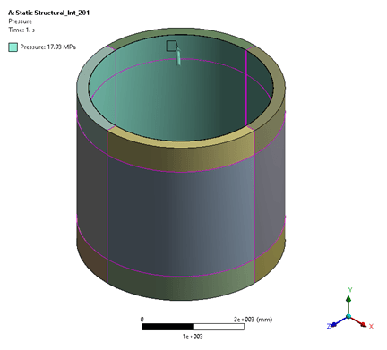
Load Case 1: Internal Pressure
Internal design pressure (17.93 MPa) applied on all wetted surfaces with:
- Design internal pressure: 17.93 MPa on all internal surfaces
- Outward thrust at shell cutout due to internal pressure
- Operating weight: 550,000 kg acting downward
- Displacement BC at shell cutout (tangential + axial restrained)

Figure 7: LC1 setup – Internal pressure + thrust + operating weight
Load Case 2: External Pressure (Vacuum)
External design pressure (0.1 MPa) with inward thrust – governs the buckling assessment:
- Design external pressure: 0.1 MPa on all outer surfaces
- Inward thrust at shell cutout due to external pressure
- Operating weight acting downward
- Displacement BC identical to LC1

Figure 8: LC2 setup — External pressure + inward thrust
6. Detailed Results
Von Mises stress distribution for both load cases. LC1 (internal pressure) produces significantly higher stresses at the dis-bonding region. The peak stress occurs where the dis-bonded clad transitions to bonded clad, creating a stress concentration.

Figure 9: Von Mises stress – LC1 full model

Figure 10: Stress at dis-bonding region – LC1

Figure 11: Stress detail at critical location — LC1

Figure 12: Von Mises stress – LC2 full model

Figure 13: Stress detail at dis-bonding – LC2
7. Stress Acceptance & Buckling Assessment
Stress acceptance per ASME VIII Div 2 Annex 2D with API 579 RSFa = 0.9:
Allowable stresses (adjusted by RSFa = 0.9):
- S = 149.84 / 0.9 = 166.48 MPa
- SPL = Sy = 230.88 / 0.9 = 256.53 MPa
- SPS = 2×Sy = 461.76 / 0.9 = 513.06 MPa
- Local failure: 4×S = 665.92 MPa
Plastic Collapse - PL Stresses
| Load Case | Location | PL (MPa) | Allowable (MPa) | Result |
|---|---|---|---|---|
| LC1 | Max stress location | 144.85 | 256.33 | PASS |
| LC2 | Max stress location | 24.4 | 256.33 | PASS |
Plastic Collapse - PL+Pb+Q Stresses
| Load Case | Location | PL+Pb+Q (MPa) | Allowable (MPa) | Result |
|---|---|---|---|---|
| LC1 | Bellow | 146.07 | 513.06 | PASS |
| LC1 | Nozzle N4 neck | 27.893 | 513.06 | PASS |
Local Failure (Cl. 5.3.2)
| Load Case | PL+Pb (MPa) | Allowable 4S (MPa) | Result |
|---|---|---|---|
| LC1 | 196.09 | 665.92 | PASS |
| LC2 | -53.53 | 665.92 | PASS |
Buckling Assessment
Linear buckling analysis with pre-stress from design loads:
- Load multiplier from eigenvalue analysis: 197.73
- Buckling load = {(0.1) + 197.73 × (0.1)} / 2.5 = 7.95 MPa
- Design external pressure: 0.1 MPa << 7.95 MPa allowable
- Result: PASS — massive safety margin (79× factor)

Figure 14: Buckling mode shape
8. Model Validation
Hoop Stress Validation
ASME VIII-2 Part 4, Clause 4.3.10.2 (Eq. 4.3.32) — hoop stress in shell away from discontinuity:
Shell OD = 4,073 mm, ID = 3,600 mm, P = 17.94 MPa
| Method | Hoop Stress (MPa) | Deviation |
|---|---|---|
| Hand Calculation | 154.48 | – |
| FEA Result | 150.0 | ~3% |
The FEA result is slightly lower than hand calculation – expected because FEA captures 3D effects including adjacent structural influence.
Global Equilibrium Check
Global force and moment equilibrium verified through ANSYS force reaction summary at boundary conditions. Total applied loads match total reaction forces within solver tolerance.
| Load Case | Location | PL+Pb+Q (MPa) | Allowable (MPa) | Result |
|---|---|---|---|---|
| LC1 | Bellow | 146.07 | 513.06 | PASS |
| LC1 | Nozzle N4 neck | 27.893 | 513.06 | PASS |

Figure 15: Hoop stress comparison – FEA vs analytical
9. Lessons Learned
Contact Modelling Defines Dis-Bonding FEA Accuracy: The frictional contact (μ=0.3) at dis-bonded regions and bonded contact at intact regions is the critical modelling decision. This dual-contact approach captures the real structural behavior where dis-bonded clad can lift under internal pressure but remains friction-constrained. Without proper contact modelling, the stress redistribution around the dis-bonding patch would be entirely wrong.
Worst-Case Modelling Provides Conservative Confidence: Modelling the entire 2.5m patch as fully dis-bonded – rather than using partial bonding based on NDT intensity maps – provides conservative results. In reality, some areas may still have partial adhesion. The worst-case approach gives high confidence in the fitness-for-service conclusion.
RSFa Factor Is Non-Negotiable for API 579: The Allowable Remaining Strength Factor (RSFa=0.9) reduces all allowable stresses by ~11%. This accounts for uncertainty in NDT data accuracy and the actual extent of dis-bonding. Forgetting this factor would produce unconservative acceptance criteria.
10. What Could Have Gone Wrong
Ignoring Contact Mechanics: Modelling the dis-bonded area without contact elements – either as fully bonded (wrong, ignores the defect) or fully disconnected (wrong, no friction restraint) – would produce fundamentally inaccurate results. Contact mechanics with appropriate friction coefficient is mandatory for dis-bonding simulation.
Skipping the Buckling Check: A dis-bonded clad layer under external pressure is essentially a thin unsupported plate susceptible to buckling. Without the eigenvalue buckling analysis, the vacuum condition would go unassessed. In this case the margin is massive (0.1 vs 7.95 MPa), but for thinner cladding this could govern.
Using Room-Temperature Material Properties: SA 336 F22 Cl 3 properties at 454°C differ significantly from room temperature – yield drops from ~310 to 230.88 MPa. Using room-temperature values would overestimate material strength and produce unconservative allowable stresses.
11. Recommendations
For Repair Planning
- No immediate repair required – stresses are well within allowable limits at 56% utilization
- Schedule repair of dis-bonded area during next planned turnaround to restore full clad integrity
- Consider weld overlay repair or clad replacement in the dis-bonded zone
For Monitoring
- Continue PAUT monitoring of the 2.5m dis-bonded zone at each turnaround
- Track any growth in the dis-bonded area – expansion beyond the current patch would require re-assessment
- Implement AE (acoustic emission) monitoring if available for continuous surveillance
For Re-Assessment Timeline
- Re-assess if operating conditions change (pressure increase, temperature excursion)
- Re-assess if dis-bonding area grows beyond the 2.5m patch based on NDT surveillance
- Recommended re-assessment interval: next scheduled inspection, or 5 years maximum
12. Limitations & Assumptions
- Dis-bonding extent based on PAUT NDT data – accuracy depends on NDT resolution and operator skill
- Entire 2.5m patch modelled as fully dis-bonded (worst-case); actual condition may have partial bonding
- Linear elastic analysis – no plastic redistribution effects considered
- Friction coefficient μ=0.3 assumed at dis-bonded interface – actual value depends on surface conditions
- No hydrogen-induced damage or creep effects included in this assessment
13. Conclusion
- All three failure modes (Plastic Collapse, Local Failure, Buckling) assessed per API 579-1 Annex 2D — ALL PASS
- Plastic collapse: PL = 144.85 MPa vs 256.33 MPa allowable (56% utilization)
- Local failure: PL+Pb = 196.09 MPa vs 665.92 MPa allowable (29% utilization)
- Buckling: 0.1 MPa vs 7.95 MPa allowable vacuum (79× safety margin)
- FEA validated against ASME hand calculation — hoop stress within ~3%
- Contact modelling (frictional at dis-bonded, bonded at intact) accurately represents structural behavior
- Equipment Tag 16-RB-00-201 is safe for continued service under current design conditions
Status: ACCEPTABLE – Equipment cleared for continued operation per API 579-1/ASME FFS-1 Level 3.
Download the Full Technical Case Study
The full technical report includes:
- API 579 Level 3 assessment of shell clad dis-bonding with multiple failure modes
- Stress evaluation for plastic collapse, local failure, and buckling
- Detailed contact modelling approach (frictional vs bonded interfaces)
- Load case definitions including internal pressure and vacuum conditions
- Stress contour plots and critical region analysis
- Validation including hoop stress comparison and equilibrium checks
- Code references including API 579-1 / ASME FFS-1 and ASME Section VIII
Please check your email inbox.