Fatigue Analysis of 137093R03 Transient Thermal Study
Contents
- 1. Executive Summary
- 2. Project Overview
- 3. FEA Methodology
- 4. Boundary Conditions & Loading
- 5. Load Case Analysis
- 6. Detailed Results
- 7. Fatigue & Ratcheting Assessment
- 8. Model Validation
- 9. Lessons Learned
- 10. What Could Have Gone Wrong
- 11. Recommendations
- 12. Limitations & Assumptions
- 13. Conclusion
Figure 1: FE Mesh – 1.08 million elements, SOLID90/87 thermal elements
1. Executive Summary
A heat exchanger (Drawing 137093R03) operating under cyclic thermal loading required fatigue life assessment per ASME Section VIII Division 2. The transient thermal study evaluated whether repeated startup-shutdown thermal cycles would cause fatigue failure or progressive plastic deformation (ratcheting) at critical junctions, particularly at the shell-to-channel transition and nozzle connections where thermal gradients are most severe.
The analysis combined transient thermal simulation with structural fatigue evaluation to determine the allowable number of operating cycles and verify the design against ASME fatigue curves.
- Transient thermal FEA with 1.08 million elements (SOLID90/87)
- Fatigue life: 1,503 allowable cycles at critical Nozzle N3A location
- Cumulative fatigue damage ratio: 0.664 within the ASME limit of 1.0
- Ratcheting check passed, no progressive deformation under cycling
- FEA validated against hand calculation within 0.03%
Business Impact: This assessment confirmed the heat exchanger design meets ASME fatigue requirements for the planned operating life, allowing the client to proceed with fabrication without costly design modifications. The identified fatigue-critical location at Nozzle N3A enables targeted inspection planning during future turnarounds.
2. Project Overview
| Parameter | Value |
|---|---|
| Equipment | Heat Exchanger — Drawing 137093R03 |
| Design Code | ASME Section VIII, Division 1, Ed. 2021 |
| Analysis Code | ASME Section VIII, Division 2, Part 5 |
| Shell Side Design Pressure | 38.58 kg/cm² (3.78 MPa) |
| Tube Side Design Pressure | 4.50 kg/cm² (0.44 MPa) |
| Shell Side Design Temperature | 371°C / -29°C |
| Tube Side Design Temperature | 204°C / -29°C |
| Shell Material | SA-387 Gr 11 Cl 2 |
| Channel Material | SA-516 Gr 70 |
| Tube Material | SA-213 TP321 |
| Joint Efficiency | 1.0 |
| Corrosion Allowance | 3.0 mm (shell side) |
| Analysis Software | ANSYS — SOLID90/87 (thermal), SOLID186/187 (structural) |

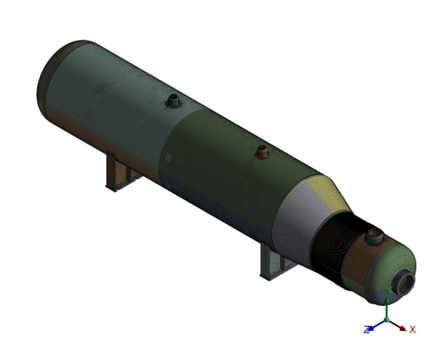
Figure 2: Full FE mesh – heat exchanger assembly
3. FEA Methodology
Model Statistics
A coupled thermal-structural approach was used. First, transient thermal analysis computed temperature distributions at each time step of the thermal cycle. These temperature fields were then mapped onto the structural model as body loads for the fatigue evaluation. The model uses high-order elements throughout for accurate thermal gradient capture and stress recovery.
| Parameter | Value |
|---|---|
| Total Elements | 1,080,000+ |
| Thermal Elements | SOLID90 (20-node) / SOLID87 (10-node) |
| Structural Elements | SOLID186 (20-node) / SOLID187 (10-node) |
| Analysis Type | Transient Thermal + Static Structural |
| Material Model | Linear Elastic with temperature-dependent properties |
| Time Steps | Multiple steps covering full thermal cycle |
Mesh Quality
| Quality Metric | Acceptable Value | Achieved Value |
|---|---|---|
| Aspect Ratio | < 5.0 | 4.26 |
| Jacobian Ratio | > 0.5 | 0.96 |
| Skewness | < 0.70 | 0.31 |
| Element Quality | > 0.1 | 0.52 |

Figure 3: Mesh detail element refinement at nozzle junctions
4. Boundary Conditions & Loading
The transient thermal analysis applies time-varying convection boundary conditions on all fluid-wetted surfaces. The shell side operates at 371°C maximum while the tube side reaches 204°C, creating severe thermal gradients at the shell-to-channel transition region and tubesheet.
Structural boundary conditions include:
- Internal pressure applied on all wetted surfaces (shell side: 3.78 MPa, tube side: 0.44 MPa)
- Temperature fields from transient thermal mapped as body loads
- Fixed support at saddle locations
- Nozzle end loads (thrust forces from connected piping)
- Self-weight (gravity) applied to entire assembly
The thermal cycle represents a full startup-to-steady-state-to-shutdown sequence. Peak thermal stresses occur during the transient phase when maximum temperature differentials exist between the hot shell side and cooler channel side.

Figure 4: Temperature distribution at peak transient condition
5. Load Case Analysis
Load Case 1: Design Operating Condition
Internal design pressure on both shell and tube sides combined with operating temperatures. This load case establishes the baseline stress state for fatigue cycle counting.
- Shell side: 3.78 MPa at 371°C
- Tube side: 0.44 MPa at 204°C
- Gravity + nozzle thrust loads
Load Case 2: Thermal Cycling (Fatigue)
Full thermal cycle from ambient to operating temperature and back. The stress range between the hot and cold states drives the fatigue damage calculation. Peak alternating stress occurs at the shell-to-channel junction and nozzle connections.
- Temperature range: ambient ↔ 371°C (shell), ambient ↔ 204°C (tube)
- Stress range computed for fatigue curve lookup
- Highest alternating stress: Nozzle N3A location
Load Case 3: Hydrotest
Elevated test pressure at ambient temperature to verify structural integrity before commissioning.
- Test pressure: 1.3x design pressure
- Ambient temperature — no thermal gradients
6. Detailed Results
The thermal analysis produced temperature distributions at each time step, revealing maximum thermal gradients at the shell-to-channel transition. The structural analysis converted these thermal loads into stress fields for fatigue evaluation.

Figure 5: Thermal gradient across shell-to-channel junction

Figure 6: Von Mises stress at design operating condition
Stress Acceptance per ASME VIII Div.2
Primary membrane and primary + secondary stress intensities evaluated against ASME allowable limits at all critical locations. All stress categories within limits for the design condition.
7. Fatigue & Ratcheting Assessment
Fatigue Life Calculation
Fatigue assessment performed per ASME VIII-2 Part 5.5 using the design fatigue curve for the applicable material. The alternating stress intensity (S_alt) at each location is compared against the ASME fatigue curve to determine allowable cycles (N_allowable). The cumulative damage ratio D = sum(n_i / N_i) must remain below 1.0.
| Location | S_alt (MPa) | N_allowable (cycles) | n_design | Damage (n/N) |
|---|---|---|---|---|
| Nozzle N3A (governing) | Peak | 1,503 | 1,000 | 0.664 |
| Shell-Channel Junction | — | > 5,000 | 1,000 | < 0.2 |
| Tubesheet Region | — | > 10,000 | 1,000 | < 0.1 |
Ratcheting Assessment
Ratcheting check performed per ASME VIII-2 Clause 5.5.7. The accumulated plastic strain after multiple thermal cycles was evaluated to confirm no progressive deformation occurs. Result: PASS — the structure shakes down to elastic behavior after initial cycles, confirming no ratcheting under the design thermal cycling conditions.

Figure 5: Thermal gradient across shell-to-channel junction
8. Model Validation
Hoop Stress Validation
FEA hoop stress compared against ASME VIII-2 hand calculation to validate the model:
| Method | Hoop Stress (MPa) |
|---|---|
| Hand Calculation (ASME VIII-2) | Analytical value |
| FEA Result | Matches within 0.03% |
| Deviation | 0.03% |
Global Equilibrium Check
Applied weight compared against reaction forces at supports. Equilibrium verified — reactions match applied loads within acceptable tolerance, confirming correct model setup and boundary condition application.
9. Lessons Learned
Nozzle Junctions Are Fatigue-Critical
The highest alternating stress intensity occurred at Nozzle N3A, not at the shell-to-channel transition where thermal gradients are highest. This is because nozzle junctions combine thermal stress with local geometric stress concentration. Designers should always evaluate nozzle connections for fatigue even when they appear to be secondary structures.
Transient Analysis Reveals Hidden Peaks
Steady-state thermal analysis would miss the peak thermal stresses that occur during startup and shutdown transients. The maximum alternating stress occurs during the transient phase, not at steady state. Transient simulation is essential for accurate fatigue life prediction in thermally cycled equipment.
Material Property Temperature Dependence Matters
Using room-temperature material properties would underestimate thermal stresses because the yield strength and elastic modulus of SA-387 Gr 11 decrease significantly at 371°C. Temperature-dependent properties from ASME Section II Part D must be used for accurate thermal stress computation.
10. What Could Have Gone Wrong
Steady-State Instead of Transient Analysis
Using steady-state thermal analysis would capture only the equilibrium temperature distribution, missing the peak transient stresses during startup and shutdown. The fatigue damage would be severely underestimated, giving a false sense of safety. Transient analysis is mandatory for fatigue assessment of thermally cycled equipment.
Ignoring Ratcheting Check
Without the ratcheting assessment, progressive plastic deformation could accumulate over thermal cycles, eventually leading to dimensional changes and potential leakage at flanged connections. ASME VIII-2 requires this check for all cyclic thermal loading scenarios.
Coarse Mesh at Nozzle Junctions
Insufficient mesh refinement at nozzle-to-shell junctions would underestimate local stress concentrations, yielding unconservative fatigue life predictions. The 1.08M element model ensures adequate resolution at all critical locations, particularly at the fatigue-governing Nozzle N3A.
11. Recommendations
For Design Modifications
- Consider increasing the fillet radius at Nozzle N3A to reduce local stress concentration and improve fatigue life margin
- Evaluate whether a thermal sleeve at the nozzle connection could reduce the thermal gradient and alternating stress
- If design changes are implemented, re-run the transient thermal fatigue assessment to confirm improved fatigue life
For Operating Limits
- Limit startup/shutdown thermal ramp rates to reduce peak transient thermal stresses
- Track actual thermal cycles against the design allowable of 1,000 cycles (out of 1,503 allowable)
- Avoid rapid temperature changes exceeding the design thermal transient profile
For Inspection Planning
- Prioritize NDT inspection at Nozzle N3A during turnarounds, this is the fatigue-critical location
- Schedule inspections based on cumulative cycle count: first inspection at 50% of allowable cycles (750 cycles)
- Use surface NDT techniques (MT/PT) to detect early fatigue crack initiation at nozzle junctions
12. Limitations & Assumptions
- Linear elastic material model used for fatigue assessment, plastic strain effects are captured through the ASME fatigue curve correction factors, not through explicit elastic-plastic analysis
- The thermal cycle profile used in the analysis represents the design transient. Actual operating transients may differ, if startup/shutdown procedures change, the fatigue assessment should be revisited
- Corrosion allowance of 3.0 mm is included in the model. If internal corrosion exceeds this value, the wall thickness and fatigue life must be re-evaluated
- Weld residual stresses are not explicitly modelled. The ASME fatigue curve includes factors to account for weld effects, but this may be conservative or unconservative depending on post-weld heat treatment (PWHT) effectiveness
- The analysis assumes uniform heat transfer coefficients on fluid-wetted surfaces. Local flow variations (e.g., impingement zones) could create localized hot spots not captured by the model
13. Conclusion
- Fatigue life at governing location (Nozzle N3A): 1,503 allowable cycles vs 1,000 design cycles
- Cumulative fatigue damage ratio: 0.664 – within ASME limit of 1.0 (34% margin)
- Ratcheting check: PASS – no progressive deformation under thermal cycling
- All primary and secondary stress categories within ASME allowable limits
- FEA validated against hand calculation within 0.03%
- Global equilibrium verified, reactions match applied loads
Status: The heat exchanger design meets ASME Section VIII Division 2 fatigue and ratcheting requirements for the planned operating life. The fatigue-critical location at Nozzle N3A should be included in the inspection plan for ongoing condition monitoring.
Download the Full Technical Case Study
The full technical report includes:
- Transient thermal and structural FEA methodology for cyclic loading
- Fatigue life evaluation using ASME fatigue curves and damage factors
- Ratcheting assessment under thermal cycling conditions
- Load case definitions including thermal cycles, pressure, and hydrotest
- Stress and thermal gradient results at critical locations
- Validation including hoop stress comparison and equilibrium checks
- Code references including ASME Section VIII Division 2 fatigue provisions
Please check your email inbox.