FEA of NTIW Heat Exchanger E-1010
Tubesheet Structural Verification | ASME VIII Div.2 Part 5
1. Executive Summary
An NTIW heat exchanger E-1010 required tubesheet structural verification under all design, operating, and hydrotest conditions. The exchanger handles a 295°F thermal differential (420°F shell vs 250°F tube side) with design pressures of 185 PSIG (shell) and 145 PSIG (tube). The analysis evaluates 10 load cases per ASME VIII Div.2 Part 5.2.2 – Protection against Plastic Collapse.
- 10 load cases: 4 design + 4 operating with thermal + 2 hydrotest
- Governing PL: 119.26 MPa vs 210.51 MPa (57% utilization) – TS RHS ligament, LC6
- Governing PL+Pb+Q: 188.11 MPa vs 421.02 MPa (45% utilization)
- Tightest margin: equivalent stress 127.45 vs 138 MPa (92% – LC8, TS RHS)
- FEA validated: hoop stress 48.11 vs 48.03 MPa (0.17% error)
- Global equilibrium: 47,578 N applied vs 47,886 N reaction – verified
All load cases pass. The tubesheet design is adequate for service.
2. Project Overview
| Parameter | Shell Side | Tube Side |
|---|---|---|
| Design Pressure | 185 PSIG (1.28 MPa) | 145 PSIG (1.0 MPa) |
| Operating Pressure | 130 PSIG (0.90 MPa) | 50 PSIG (0.34 MPa) |
| Design Temperature | 420°F (216°C) | 250°F (121°C) |
| Operating Temp (In/Out) | 359/175°F | 90/105°F |
| Hydrotest | 443.5 PSIG (3.06 MPa) | 443.5 PSIG (3.06 MPa) |
| Corrosion Allowance | 3.175 mm | 3.175 mm |
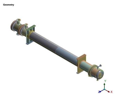
Figure 1: NTIW Heat Exchanger E-1010 – 3D geometry

Figure 2: Tubesheet and internal detail
3. Materials
| Component | Material | S (MPa) | Sy (MPa) |
|---|---|---|---|
| Shell, Head, Channel | SA-516 Gr 70 | 138 | 222.51 |
| Tubesheet | SA 765 Gr II | 137.37 | 210.51 |
| Tubes | SA 179 | 92.4 | 152.13 |
| Nozzles | SA 106 Gr B | 118 | 204.51 |
All material properties are per ASME Sec II Part D, Ed. 2023 at maximum design temperature (215.55°C). Elastic modulus: 191,544 MPa. Poisson’s ratio: 0.3. Density: 7,750 kg/m³.
4. FEA Methodology
Linear static FEA per ASME VIII Div.2 Part 5.2.2. The full exchanger is modeled with SOLID186 (20-node) elements. Stress classification uses the SCL method at critical tubesheet locations: LHS ligament, LHS center thickness, LHS OTL, and RHS ligament. Stresses are decomposed into Pm, PL, Pb, and Q components per ASME Figure 5.1.
| Parameter | Value |
|---|---|
| Design Code | ASME VIII Div.1 Ed. 2023 |
| FEA Code | ASME VIII Div.2 Part 5 Ed. 2023 |
| Element Type | SOLID186 (20-node, 3D) |
| Analysis Type | Linear Static |
| SCL Locations | LHS Ligament, Center, OTL, RHS Ligament |
| Software | ANSYS Mechanical |

Figure 3: FE mesh – full model

Figure 4: Tubesheet mesh detail
5. Load Cases
10 load cases per ASME VIII Div.2:
- LC1: Tube side max + Shell side min + gravity + thrust + NPL + moment
- LC2: Shell side max + Tube side min (same mechanical loads)
- LC3: Both sides max pressure
- LC4: Both sides min pressure
- LC5: Operating (tube max, shell min) + thermal differential
- LC6: Operating (shell max, tube min) + thermal differential
- LC7: Operating (both max) + thermal differential
- LC8: Full vacuum (both FV) + thermal differential
- LC9: Hydrotest shell side (443.5 PSIG) + hydrostatic head
- LC10: Hydrotest tube side (443.5 PSIG) + hydrostatic head
6. Boundary Conditions
- Fixed support: all DOFs restrained
- Sliding saddle: axial + tangential fixed, radial free
- Standard Earth gravity applied to full model
- Nozzle piping loads (thrust, moment) at connections
- Shell/tube thermal profile per operating temperatures

Figure 5: Channel side pressure application

Figure 6: Fixed support boundary condition

Figure 7: Thermal profile – temperature distribution
7. Results - Deformation
The deformation patterns confirm expected structural behavior under all load cases. Maximum deformation occurs under operating+thermal conditions due to differential thermal expansion between shell and tube sides.

Figure 8: Total deformation – LC1

Figure 9: Total deformation – LC2
8. Results - Stress
Maximum stresses occur at tubesheet ligament regions. The RHS ligament under LC6 (shell max operating + thermal) governs with PL of 119.26 MPa.

Figure 10: Tubesheet LHS stress – LC1

Figure 11: Tubesheet RHS stress – LC1

Figure 12: SCL for tubesheet LHS – LC2
9. Stress Acceptance
Primary Local Membrane (PL)
| LC | Location | PL (MPa) | Allowable | Result |
|---|---|---|---|---|
| LC2 | TS RHS Ligament | 60.87 | 210.51 | Pass |
| LC5 | TS LHS Ligament | 68.26 | 210.51 | Pass |
| LC6 | TS LHS Ligament | 86.74 | 210.51 | Pass |
| LC6 | TS RHS Ligament | 119.26 | 210.51 | Pass |
| LC8 | TS LHS Ligament | 73.94 | 215.20 | Pass |
Primary + Secondary (PL+Pb+Q)
| LC | Location | PL+Pb+Q | Allowable | Result |
|---|---|---|---|---|
| LC2 | TS RHS Ligament | 171.83 | 421.02 | Pass |
| LC6 | TS RHS Ligament | 188.11 | 421.02 | Pass |
| LC8 | TS LHS Ligament | 120.88 | 430.40 | Pass |
Hydrotest Membrane & Bending
| LC | Check | Value (MPa) | Allowable | Result |
|---|---|---|---|---|
| LC9 | Pm (Shell) | 85.24 | 235.8 | Pass |
| LC10 | Pm (Channel) | 53.05 | 235.8 | Pass |
| LC8 | Pm+Pb (Shell) | 89.78 | 353.7 | Pass |
Equivalent Stress at Tubesheet
| LC | Location | Equiv. (MPa) | Allowable | Result |
|---|---|---|---|---|
| LC1 | TS LHS | 78.52 | 137.37 | Pass |
| LC5 | TS RHS | 126.34 | 138 | Pass |
| LC8 | TS RHS | 127.45 | 138 | Pass |
10. Model Validation
Hoop Stress Validation
| Method | Hoop Stress (MPa) | Error |
|---|---|---|
| Hand Calc (ASME VIII Div.2 Eq. 4.3.32) | 48.026 | – |
| FEA (ANSYS) | 48.109 | 0.17% |
Global Equilibrium
| Parameter | Value |
|---|---|
| Applied Weight | 47,577.5 N (4,849.9 kg) |
| Fixed Support Reaction | 24,432 N |
| Sliding Support Reaction | 23,454 N |
| Total Reaction | 47,886 N |
| Equilibrium | Verified ✓ |

Figure 13: Hoop stress – FEA vs analytical
11. Lessons Learned
Tightest Margin Under Operating+Thermal: Equivalent stress at LC8 reached 92% utilization – higher than any design pressure case. Thermal differential effects can shift the governing condition from design to operating conditions.
SCL Location Selection: Stress varied 10-50× between center thickness and ligament locations. Wrong SCL placement would misrepresent structural adequacy.
NTIW Asymmetry: RHS ligament stress was 50-100% higher than LHS for the same load case. Both sides must be independently evaluated.
12. What Could Have Gone Wrong
Ignoring Thermal Loads: Design-only analysis would show 60.87 MPa governing – half the actual 119.26 MPa from operating+thermal.
Single SCL Location: Center-thickness SCL shows 2-7 MPa vs actual 119.26 MPa at ligament – an order of magnitude difference.
Wrong Support Modeling: Fixed sliding saddle would introduce artificial axial stresses; too-flexible fixed support would fail equilibrium.
13. Recommendations
- Monitor operating temperatures – thermal differential is the dominant stress driver
- If corrosion allowance is consumed, re-evaluate with reduced ligament width
- Consider fatigue analysis for cyclic startup/shutdown thermal transients
- Verify nozzle piping loads remain within design assumptions after commissioning
14. Conclusion
- All 10 load cases pass ASME VIII Div.2 Part 5 stress acceptance
- Governing PL: 119.26 MPa vs 210.51 MPa at TS RHS ligament (LC6)
- Governing PL+Pb+Q: 188.11 MPa vs 421.02 MPa (LC6)
- Tightest margin: 127.45 vs 138 MPa at TS RHS (92%, LC8)
- Validated: hoop 48.11 vs 48.03 MPa (0.17%), equilibrium verified
- NTIW Heat Exchanger E-1010 cleared for all operating conditions
Status: ACCEPTABLE – Tubesheet design adequate.
Download the Full Technical Case Study
The full technical report includes:
- Detailed evaluation of all 10 load cases including design, operating, thermal, vacuum, and hydrotest conditions
- Stress classification (SCL) results at critical tubesheet ligament locations
- PL and PL+Pb+Q stress acceptance checks as per ASME VIII Division 2
- Thermal differential impact analysis between shell and tube sides
- Stress contour plots and deformation results for governing load cases
- Validation including hoop stress comparison and global equilibrium checks
- Code references including ASME Section VIII Division 2 (Part 5)
Please check your email inbox.