FEA of Marine Loading Arm Deck 2
33 Load Cases | 3 Arms | 7 Positions
1. Executive Summary
A Marine Loading Arm (MLA) Deck 2 system with 3 loading arms required structural verification across its full operating envelope before marine terminal commissioning. Each arm consists of flow piping (A 106 Gr B), structural supports (1.4404 stainless), and bolted connections (1.4462 duplex) – operating at 1.79 MPa and 93°C while articulating through multiple angular positions.
- 33 load cases: 3 arms × 7 positions × 3 load types (wind, seismic, hydrotest)
- Worst-case position: 53.68° articulation – found by sweeping all positions
- Governing: PL+Pb+Q = 379.49 MPa vs 445.6 MPa (85% utilization)
- All hydrotest: max Pm = 53.65 MPa vs 228 MPa (23% utilization)
- Global equilibrium: 0.001–0.007% error for all 3 arms
All 33 load cases pass ASME VIII-2 Part 5 stress acceptance. MLA Deck 2 is cleared for commissioning.
2. Project Overview
| Parameter | Value |
|---|---|
| Equipment | Marine Loading Arm Deck 2 — 3 Arms |
| Design Codes | ASME B31.3 + ASME VIII-2 Part 5 (Ed. 2023) |
| Design Pressure | 1.79 MPa |
| Hydrotest Pressure | 2.69 MPa |
| Design Temperature | 93°C |
| Pipe Material | A 106 Gr B |
| Structure Material | 1.4404 |
| Bolt Material | 1.4462 |
| Weight per Arm | ~30,500–30,700 kg |
| Positions | 7 angular positions |
| Total Load Cases | 33 |
| Elements | SHELL181 + SOLID186 |
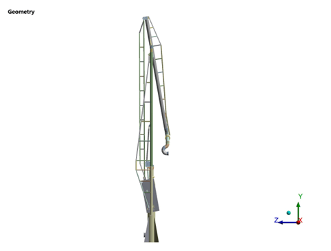
Figure 1: MLA Deck 2 – 3D assembly

Figure 2: Original operating position
3. FEA Methodology
Linear static FEA per ASME VIII-2 Part 5.2. SHELL181 elements model the structural frame (plates, flanges), SOLID186 models the flow pipe and nozzle junctions where accurate stress capture is required. The operating envelope sweep strategy evaluated LA1 at all 7 positions first to identify 53.68° as the worst case, then analyzed LA2 and LA3 at original and worst-case positions.
| Parameter | Value |
|---|---|
| Elements | SHELL181 (structure) + SOLID186 (pipe/nozzle) |
| Analysis Type | Linear Static |
| Allowable: Pipe | S=138 MPa, Sy=222.8 MPa |
| Allowable: Structure | S=145.94 MPa, Sy=205.16 MPa |
| Allowable: Bolt | S=247.28 MPa, Sy=370.98 MPa |

Figure 3: Full FE mesh – SHELL181 + SOLID186

Figure 4: Flow pipe mesh detail
4. Boundary Conditions & Loading
Each load case includes combinations of:
- Standard Earth gravity (self-weight ~30,700 kg per arm)
- Internal/hydrotest pressure on wetted surfaces
- Hydrostatic pressure from internal fluid
- Nozzle thrust from pressure cutout
- Wind pressure (lateral)
- Seismic acceleration (dynamic equivalent)
- Fixed saddle (all DOFs) + sliding saddle (vertical only)

Figure 5: Internal pressure application

Figure 6: Wind loading on arm
5. Load Case Analysis
Load Case Structure
LA1: LC1-21 (7 positions × 3 types). LA2: LC22-27 (original + 53.68° × 3). LA3: LC28-33 (original + 53.68° × 3).
| Position | LC (Wind) | LC (Seismic) | LC (Hydrotest) |
|---|---|---|---|
| Original | LC1 | LC2 | LC3 |
| 25.5° | LC4 | LC5 | LC6 |
| 105.25° | LC7 | LC8 | LC9 |
| 140.79° | LC10 | LC11 | LC12 |
| 134.38° | LC13 | LC14 | LC15 |
| 77.80° | LC16 | LC17 | LC18 |
| 53.68° (worst) | LC19 | LC20 | LC21 |

Figure 7: Worst-case position (53.68°)
6. Detailed Results
Von Mises stress results for all load cases. Nozzle-to-pipe junctions consistently govern across all arms and positions. The governing stress location is at the flow pipe connection where pressure thrust combines with bending from arm weight and environmental loads.

Figure 8: Von Mises – LC1 (original, wind + pressure)

Figure 9: Mid-surface stress – LC1

Figure 10: Von Mises – LC2 (seismic + pressure)

Figure 11: Worst case – LC5 at 25.5°+seismic

Figure 12: Deformation – LC1
7. Stress Acceptance
ASME VIII-2 Part 5.2 — plastic collapse protection. βT=0.95, Γmin=1.35.
Primary Membrane (Pm) - Hydrotest
| LC | Pm (MPa) | Allowable (MPa) | Result |
|---|---|---|---|
| LC3 | 51.10 | 228 | PASS |
| LC6 | 50.41 | 228 | PASS |
| LC9 | 52.15 | 228 | PASS |
| LC12 | 53.65 | 228 | PASS |
| LC15 | 49.57 | 228 | PASS |
| LC18 | 50.65 | 228 | PASS |
| LC21 | 50.14 | 228 | PASS |
| LC24 | 51.43 | 228 | PASS |
| LC27 | 50.54 | 228 | PASS |
| LC30 | 49.39 | 228 | PASS |
| LC33 | 48.78 | 228 | PASS |
Primary + Secondary (PL+Pb+Q) - Design
| LC | Location | PL+Pb+Q (MPa) | Allowable (MPa) | Result |
|---|---|---|---|---|
| LC26 | Nozzle-pipe | 379.49 | 445.6 | PASS |
| LC25 | Nozzle-pipe | 368.85 | 445.6 | PASS |
| LC16 | Nozzle-pipe | 361.18 | 445.6 | PASS |
| LC5 | Bolt | 284.12 | 740.96 | PASS |
| LC32 | Nozzle-pipe | 289.31 | 445.6 | PASS |
Pm+Pb - Hydrotest
| LC | Pm+Pb (MPa) | Allowable (MPa) | Result |
|---|---|---|---|
| LC3 | 52.07 | 324 | PASS |
| LC9 | 53.30 | 324 | PASS |
| LC12 | 52.40 | 324 | PASS |
| LC33 | 52.65 | 324 | PASS |
8. Model Validation
Global Equilibrium
| Arm | Applied (N) | Reaction (N) | Error |
|---|---|---|---|
| LA1 | 298,940 | 298,934 | 0.001% |
| LA2 | 301,333 | 301,339 | 0.001% |
| LA3 | 299,480 | 299,502 | 0.007% |
Applied gravity loads match reaction forces within solver precision for all three arms.

Figure 13: Equilibrium verification – reaction summary
9. Lessons Learned
Worst Case ≠ Full Extension: The governing stress occurs at 53.68° – not at maximum extension. The arm’s center of gravity at this angle creates the maximum lever arm at the pivot, producing higher bending moments than at the extremes. Without a systematic position sweep, this would be missed.
Mixed SHELL+SOLID Strategy: SHELL181 for structural frame, SOLID186 for pipe/nozzle junctions. Pure solid would be prohibitively expensive for 33 LCs; pure shell would miss nozzle-junction stress concentrations.
Three Load Types Are All Necessary: Wind creates lateral bending, seismic adds inertial forces, hydrotest has highest pressure. Each governs at different locations — checking only one misses the others.
10. What Could Have Gone Wrong
Checking Only Extreme Positions: Missing the 53.68° worst case. Stress difference can be 15-30%, enough to change pass/fail for a design near its limits.
Ignoring Nozzle-Pipe Junctions: A beam-based or shell-only analysis would underestimate local stresses at governing locations where pipe connects to structure.
Single Load Combination: Omitting wind/seismic would make the design appear 30-40% more conservative than it actually is. At 85% utilization, this margin matters.
11. Recommendations
For Design Optimization
- Nozzle-pipe junctions are the governing locations – consider local reinforcement if design margins need to be increased
- Operating envelope of 53.68° should be flagged in operating procedures as the most stressed position
- Structural supports at the fixed saddle have ample margin – potential weight reduction opportunity
For Installation & Commissioning
- Verify field welds at nozzle-pipe junctions meet quality requirements – these are the most stressed locations
- Confirm alignment of fixed/sliding saddle supports matches FEA boundary conditions
- Pre-commission hydrotest per LC3/6/9 protocol – stresses are well within limits at 23% utilization
For Operations
- Include periodic NDE inspection at nozzle-pipe junctions in the maintenance schedule
- Monitor bolt preload at 1.4462 duplex connections – these see 284 MPa under seismic events
- Review wind loading assumptions if operational wind speeds exceed design basis
12. Limitations & Assumptions
- Linear elastic analysis – no plasticity, no geometric nonlinearity
- Wind and seismic loads applied as static equivalents, not time-history dynamic
- Friction at sliding saddle not modeled – assumed frictionless sliding
- Component connections assumed perfect (continuous weld, no bolt slip)
- Temperature effects limited to material property reduction at 93°C
13. Conclusion
- All 33 load cases pass ASME VIII-2 Part 5 stress acceptance criteria
- Governing: LC26 PL+Pb+Q = 379.49 MPa vs 445.6 MPa (85% utilization)
- All hydrotest: max Pm = 53.65 MPa vs 228 MPa (23% utilization)
- Worst-case position: 53.68° — identified through systematic position sweep
- Global equilibrium verified: 0.001–0.007% for all 3 loading arms
- SHELL181+SOLID186 hybrid approach captures both structural frame and nozzle-junction stresses
- Marine Loading Arm Deck 2 is cleared for commissioning
Status: ACCEPTABLE – MLA Deck 2 structurally adequate for all operating positions.
Download the Full Technical Case Study
The full technical report includes:
- Detailed evaluation of all 33 load cases across multiple arm positions
- Stress results for pipe, structure, and bolt components under combined loading
- Operating envelope analysis identifying governing positions
- Load combinations including pressure, wind, seismic, and hydrotest
- FEA modeling approach using SHELL and SOLID elements
- Validation including global equilibrium and reaction checks
- Code references including ASME B31.3 and ASME Section VIII Division 2
Please check your email inbox.