
FEA of Post Weld Heat Treatment (PWHT)
Transient Thermal & Structural Analysis at 620°C
Contents
1. Executive Summary
This case study documents the FEA validation of a pressure vessel undergoing local PWHT at 620°C. The coupled transient thermal and static structural analysis confirms the vessel can safely undergo heat treatment without temporary supports or stiffeners.
- Maximum Y-deformation: 69.562 mm – negligible vs vessel size, no sagging or ovality
- PL+Pb+Q: 69.71 MPa vs 300 MPa allowable – only 23.2% utilization
- Coupled transient thermal + structural analysis captures full PWHT cycle
- Temperature-dependent properties from ASME II-D used (20°C to 700°C)
- All mesh quality checks pass per ANSYS best practices
- No temporary internal supports needed – saves fabrication cost
2. Industry Background
PWHT is mandatory for carbon steel pressure vessels per ASME VIII when wall thickness exceeds code limits or the vessel serves hydrogen, caustic, or high-temperature applications. At 620°C, SA-516 Gr65 yield strength drops from 260 MPa to 146 MPa – a 44% reduction. The vessel must support its own weight at this reduced strength without excessive sagging, ovality, or local buckling. FEA is essential because hand calculations cannot capture the complex interaction between thermal expansion, gravity-induced deformation, and material softening.
3. Project Overview
Design Parameters
| Parameter | Value |
|---|---|
| PWHT Temperature | 620°C |
| Soaking Time | 90 minutes |
| Heating/Cooling Rate | 110°C/hr (up to 400°C) |
| Initial Temperature | 22°C |
| Design Code | ASME VIII Div.1 / Div.2 Part 5 |
Materials
| Component | Material | Sy @ 620°C | S @ 620°C | Density |
|---|---|---|---|---|
| Shell, Dish End, Skirt | SA-516 Gr65 | 146 MPa | 12.7 MPa | 7750 kg/m³ |
| Nozzles, Flanges | SA-105 | 150 MPa | 12.9 MPa | 7750 kg/m³ |
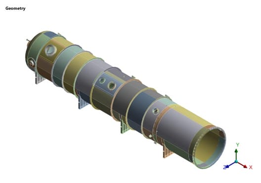
Figure 1: 3D model of the pressure vessel

Figure 2: 3D view with GAD reference
4. FEA Methodology
A coupled transient thermal + static structural analysis was performed in ANSYS Workbench. Step 1: Transient thermal analysis simulated the complete PWHT cycle (22°C → 620°C → 22°C) using temperature-dependent thermal properties. Step 2: The temperature field was imported as a body load into the structural model with self-weight and saddle boundary conditions.
Mesh Quality
| Check | Target | Achieved | Status |
|---|---|---|---|
| Aspect Ratio | < 5 | 4.2611 | PASS |
| Jacobian Ratio | > 0.5 | 1.0687 | PASS |
| Skewness | < 0.70 | 0.38004 | PASS |
| Element Quality | > 0.1 | 0.6067 | PASS |

Figure 3: FE mesh – isometric view

Figure 4: Mesh refinement at critical regions
5. Boundary Conditions
- Fixed support at first saddle (prevent rigid body motion)
- Displacement BCs at remaining saddles – free axial, restricted tangential
- Standard earth gravity (full self-weight)
- Imported body temperature from transient thermal analysis

Figure 5: Gravity applied

Figure 6: Fixed support

Figure 7: Transient thermal conditions
6. Load Case Analysis
Single load case (LC-1): Fixed support + displacement BCs + gravity + imported transient thermal (620°C PWHT cycle). This is a fabrication process, not an operating condition – no internal pressure, wind, or seismic during PWHT.
7. Detailed Results
Deformation Results
| Direction | Value | Assessment | Status |
|---|---|---|---|
| Total | Per contour | Acceptable | PASS |
| X-Axis | Per contour | Acceptable | PASS |
| Y-Axis (Sagging) | 69.562 mm | No sagging/ovality | PASS |
| Z-Axis | Per contour | Acceptable | PASS |

Figure 8: Total deformation

Figure 9: Y-direction deformation (sagging check)
Stress Results
| LC | Location | PL+Pb+Q | Allow | Util | Status |
|---|---|---|---|---|---|
| LC-1 | Max Stress | 69.71 MPa | 300 MPa | 23.2% | PASS |

Figure 10: Von Mises stress contour
8. SCL Analysis

Figure 11: SCL at maximum stress location
9. Model Validation
For PWHT analysis, validation relies on mesh quality checks (all pass), temperature-dependent material properties from ASME II-D, thermal cycle input verified against PWHT procedure Rev.02, and boundary conditions matching the physical support arrangement.
10. Lessons Learned
- Material softening is the primary concern – 44% yield strength reduction at 620°C.
- Deformation assessment (sagging/ovality) is more critical than stress in PWHT.
- Transient thermal analysis is essential – steady-state would miss temperature gradients.
- Low utilization (23.2%) confirms no temporary stiffeners needed.
11. What Could Have Gone Wrong
- Excessive sagging in longer/thinner vessels requiring barrel supports.
- Ovality from asymmetric heating in local PWHT.
- Saddle sliding due to thermal expansion.
- Nozzle distortion from differential expansion.
12. Recommendations
- No temporary supports needed – 23.2% utilization confirms adequate margin.
- Monitor saddle sliding – ensure travel range for thermal expansion.
- Verify heating uniformity with thermocouples.
- Post-PWHT inspection – check roundness and nozzle alignment.
13. Limitations & Assumptions
| Assumption | Justification |
|---|---|
| Linear static structural | Per ASME VIII-2 Part 5.2 |
| No internal pressure during PWHT | Fabrication process, not operating |
| Uniform temperature zones | Conservative approach |
| No creep analysis | 90 min too short for significant creep at 620°C |
| No wind/seismic | Controlled fabrication environment |
14. Conclusion
The coupled transient thermal and structural FEA confirms the vessel is structurally adequate for PWHT at 620°C. Maximum Y-deformation of 69.562 mm is negligible — no sagging or ovality. PL+Pb+Q of 69.71 MPa vs 300 MPa allowable gives only 23.2% utilization. The vessel is approved for PWHT without temporary internal supports.
Download the Full Technical Case Study
The full technical report includes:
- Coupled transient thermal and structural FEA methodology for PWHT cycle
- Temperature-dependent material properties and thermal cycle modeling
- Deformation and sagging assessment under high-temperature conditions
- Stress evaluation (PL+Pb+Q) with ASME allowables
- Load case definition including thermal cycle and self-weight
- Stress contour plots, deformation results, and SCL evaluation
- Validation including mesh quality checks and boundary condition verification
- Code references including ASME Section VIII Division 2 (Part 5)
Please check your email inbox.