FEA of Reboiler, Condenser & Column
ASME Section VIII Division 2 Part 5 Stress Analysis
Contents
1. Executive Summary
This case study documents the comprehensive FEA-based structural validation of a Reboiler, Condenser and Column assembly (HR-18203) for deployment in a petrochemical processing facility. The 39.6-ton operating weight assembly, supported on saddle and lug arrangements, required analysis beyond standard pressure vessel calculations to address combined pressure, gravity, wind, seismic, and thermal loading at an operating temperature of 400°C.
Key Outcomes:
- All five load cases passed ASME Section VIII Division 2 Part 5 stress acceptance criteria
- Saddle base is the governing location – PL+Pb+Q of 324.03 MPa vs 338 MPa (95.9% utilization under LC-3)
- Dish end second most critical – 222.24 MPa vs 236 MPa (94.2% under LC-1)
- Hoop stress validation exact – 36.77 MPa FEA vs analytical (0.00% error)
- Mesh convergence confirmed within 0.13% across three mesh densities
- Global equilibrium verified – applied weight matches reaction forces
Business Impact: FEA analysis provided documented evidence for regulatory approval per ASME VIII-2, identified the saddle base as requiring priority inspection during service, and confirmed the design is adequate for fabrication without modifications.
2. Industry Background
Distillation columns with integrated reboilers and condensers are fundamental to petrochemical and chemical processing. Column HR-18203 is a feed recovery column with an attached reboiler (55.6 m² surface area) and primary condenser, operating at elevated temperatures and pressures in hydrocarbon processing service. These multi-component assemblies represent some of the most structurally complex equipment in a process plant because they combine multiple pressure boundaries with diverse support configurations.
The structural challenge lies in the multi-body load transfer path. Forces from the column (20,300 kg) pass through the connection to the reboiler (15,760 kg), which sits on saddle supports. The condenser (3,403 kg) adds additional eccentric loading. Wind and seismic forces create overturning moments that stress saddle connections asymmetrically, while the 400°C operating temperature induces thermal stresses.
3. Project Overview
Design Parameters
| Parameter | Column/Reboiler | Condenser Shell | Condenser Tube |
|---|---|---|---|
| Design Temp | 400°C | 400°C | 300°C |
| Operating Temp | 370°C | 370°C | 270°C |
| Design Pressure (Int) | 0.4903 MPa | 0.4903 MPa | 0.7845 MPa |
| Shop Hydrotest | 1.1088/0.8217 MPa | 0.7641 MPa | 1.0199 MPa |
| Joint Efficiency | 0.85/NA & 1/1 | 0.85 | 0.85/1 |
Weight Summary
| Component | Weight |
|---|---|
| Reboiler | 15,760 kg |
| Column | 20,300 kg |
| Condenser | 3,402.61 kg |
| Total (ANSYS) | 39,649 kg (388,957 N) |
Materials of Construction
| Component | Material | E (MPa) | S (MPa) | Sy (MPa) |
|---|---|---|---|---|
| Main Shell | SA-240 GR 304 | 169,000 | 79.2 | 118 |
| Supports | IS 2062 GR. B | 171,000 | 113 | 169 |
| Flanges | SA-266 | 171,000 | 89.1 | 143 |

Figure 8: Von Mises – LC1 (original, wind + pressure)
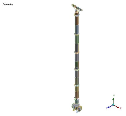
Figure 2: GAD reference
4. FEA Methodology
A comprehensive 3D finite element model was developed in ANSYS Workbench using SOLID186 (20-node, quadratic hexahedral) elements. The complete model comprises 798,395 elements. Structured mesh refinement was applied at all critical connection zones including saddle base, nozzle junctions, and lug support attachments.
Mesh Quality
| Check | Target | Achieved | Status |
|---|---|---|---|
| Aspect Ratio | < 5 | 4.0935 | PASS |
| Jacobian Ratio | > 0.5 | 0.84388 | PASS |
| Skewness | < 0.70 | 0.43465 | PASS |
| Element Quality | > 0.1 | 0.63333 | PASS |

Figure 3: FE mesh with structured refinement
Per ASME Section VIII Division 2, Part 5, stress linearization (SCL) was performed at six critical locations: saddle base, nozzle junction, shell body, dish end, column body, and lug support attachment. Pm, PL, Pb, and Q stress components were extracted and compared against allowable limits.
5. Boundary Conditions
- Saddle supports: Fixed saddle (bonded) and sliding saddle (frictionless)
- Lug support BCs: Free in radial/axial, restricted in tangential direction
- Guide supports at 11,462 mm and 21,620 mm from reboiler base
- Wind: Shear and moment on column and reboiler
- Seismic: 234.51 mm/s² in Z-direction

Figure 4: Boundary conditions for LC-1

Figure 5: Thermal boundary conditions
6. Load Case Analysis
| Load Case | Description | Loads |
|---|---|---|
| LC-1 | Internal Pressure + Wind | 0.4903 MPa + Gravity + Wind Shear/Moment + 400°C |
| LC-2 | Internal Pressure + Seismic | 0.4903 MPa + Gravity + 234.51 mm/s² seismic + 400°C |
| LC-3 | External Pressure + Wind | Full Vacuum + Gravity + Wind + 400°C (GOVERNING) |
| LC-4 | External Pressure + Seismic | Full Vacuum + Gravity + Seismic + 400°C |
| LC-5 | Internal Pressure + Seismic (Ambient) | 0.4903 MPa + Seismic + 22°C |
7. Detailed Results
General Membrane Stress (Pm)
| LC | Location | Pm (MPa) | Allow (MPa) | Util. | Status |
|---|---|---|---|---|---|
| LC-1 | Shell | 53.95 | 67.32 | 80.1% | PASS |
| LC-2 | Shell | 53.90 | 67.32 | 80.1% | PASS |
| LC-3 | Shell | 42.40 | 67.32 | 63.0% | PASS |
| LC-4 | Shell | 42.33 | 67.32 | 62.9% | PASS |
| LC-5 | Shell | 33.23 | 67.32 | 49.4% | PASS |
Primary + Secondary Stress (PL+Pb+Q)
| LC | Location | PL+Pb+Q (MPa) | Allow (MPa) | Util. | Status |
|---|---|---|---|---|---|
| LC-1 | Shell Nozzle | 101.82 | 338 | 30.1% | PASS |
| LC-1 | Saddle Base | 314.75 | 338 | 93.1% | PASS |
| LC-1 | Shell | 109.42 | 236 | 46.4% | PASS |
| LC-1 | Dish End | 222.24 | 236 | 94.2% | PASS |
| LC-1 | Column | 122.91 | 236 | 52.1% | PASS |
| LC-3 | Saddle Base | 324.03 | 338 | 95.9% | PASS |
| LC-3 | Shell Nozzle | 137.21 | 338 | 40.6% | PASS |
| LC-5 | Shell | 108.78 | 236 | 46.1% | PASS |
| LC-5 | Dish End | 122.10 | 236 | 51.7% | PASS |

Figure 6: Von Mises stress at nozzle junction

Figure 7: Stress at shell and lug region

Figure 8: Total deformation under LC-1
8. SCL Analysis

Figure 9: SCL analysis at dish end
9. Model Validation
Hoop Stress Validation
Per ASME Sec. VIII Div.2, Part 4, Clause 4.3.10.2 (Eq. 4.3.32): Analytical hoop stress = 36.77 MPa. FEA hoop stress = 36.77 MPa. Error = 0.00% — exact match.

Figure 10: Hoop stress verification
Applied Weight (ANSYS): 388,957 N (39,649 kg)
Reaction Forces: 200,430 + 2,570.4 + 189,890 = 392,890.4 N
Status: EQUILIBRIUM ACHIEVED
Global Equilibrium
Applied Weight (ANSYS): 388,957 N (39,649 kg)
Reaction Forces: 200,430 + 2,570.4 + 189,890 = 392,890.4 N
Status: EQUILIBRIUM ACHIEVED
Mesh Sensitivity Study
Applied Weight (ANSYS): 388,957 N (39,649 kg)
Reaction Forces: 200,430 + 2,570.4 + 189,890 = 392,890.4 N
Status: EQUILIBRIUM ACHIEVED
| Sr. | Elements | Von Mises (MPa) | % Error |
|---|---|---|---|
| 1 | 810,853 | 256.44 | 0.13% |
| 2 | 798,395 (Selected) | 256.78 | — |
| 3 | 785,475 | 256.96 | 0.07% |

Figure 11: Mesh convergence
10. Lessons Learned
- Peak stress at lug supports requires probe evaluation – contour maximums at geometric singularities should not be used for acceptance.
- Saddle base is the critical location – consistently highest utilization (up to 95.9%) across all load cases.
- External pressure + wind governs – LC-3 produced higher saddle stresses than LC-4 (seismic).
- Column thrust forces are essential for model stability under pressure loading.
11. What Could Have Gone Wrong
- Saddle base overstress – at 95.9% utilization, additional nozzle loads could push beyond limits.
- Dish end stress concentration – 94.2% utilization leaves minimal margin for unaccounted piping loads.
- Thermal ratcheting – cyclic start-up/shutdown at 400°C could cause progressive deformation.
- Guide support misalignment – could redistribute loads unfavorably.
12. Recommendations
- Ensure full-penetration welds at saddle-to-shell and lug-to-shell connections with NDE.
- Verify guide support alignment at 11,462 mm and 21,620 mm from reboiler base.
- Prioritize periodic inspection at saddle base and dish end where utilization exceeds 90%.
- Any additional attachments near saddle zone should be re-evaluated by FEA.
13. Limitations & Assumptions
| Assumption / Limitation | Justification |
|---|---|
| Linear static analysis only | Per ASME VIII-2 Part 5.2 |
| Uniform temperature zones | Conservative approach |
| Piping reaction loads not included | Separate piping stress analysis |
| Joint efficiency applied | 0.85 shell, 1.0 nozzle/lug |
| No fatigue assessment | Requires cycle count data |
| Column thrust forces considered | Essential for stability |
14. Conclusion
The FEA of Reboiler, Condenser and Column HR-18203 has been completed successfully per ASME Section VIII, Division 2, Part 5 (Ed. 2023). All five load cases pass stress acceptance criteria. The governing utilization is 95.9% at the saddle base under LC-3 (external pressure + wind). FEA has been validated with exact hoop stress match and mesh convergence within 0.13%.
The design is adequate for the specified operating conditions. The structure is approved for fabrication subject to the recommendations outlined above.
Download the Full Technical Case Study
The full technical report includes:
- Detailed analysis of all load cases including pressure, wind, seismic, vacuum, and thermal effects
- Stress results and SCL evaluation at critical locations (saddle, nozzle, dish end, column)
- Stress contour plots and deformation results across the full assembly
- Load transfer analysis across multi-component equipment (reboiler, condenser, column)
- FEA modeling approach with mesh refinement and boundary conditions
- Validation including hoop stress comparison, mesh convergence, and equilibrium checks
- Code references including ASME Section VIII Division 2 (Part 5)
Please check your email inbox.