In engineering practice, the terms Root Cause Analysis (RCA) and Failure Analysis (FA) are often used interchangeably; however, they are distinct concepts. This misunderstanding is common across industries, even among experienced maintenance and reliability professionals. The result? Teams fix the symptom of a failure but leave the actual cause untouched, only to face the same problem again months later.
In high-risk sectors such as oil and gas, petrochemicals, power generation, and manufacturing, this distinction has a direct impact on safety, cost, and regulatory compliance. A single unresolved failure can lead to catastrophic downtime, environmental hazards, or violations of process safety standards. Understanding whether a team needs Failure Analysis or RCA can mean the difference between preventing recurrence and simply restoring operation.
This blog focuses on working engineers and plant reliability teams who routinely deal with complex equipment, pressure vessels, piping systems, heat exchangers, compressors, pumps, and turbines. It’s written for those who must interpret failure data, justify repair decisions, and document investigations to meet API 579-1/ASME FFS-1 (Fitness for Service) and ISO 14224 (Reliability Data Collection) requirements.
What Failure Analysis Really Means in Practice
Once a failure occurs, engineers are under immediate pressure to find out what went wrong and bring the system back online. That’s where Failure Analysis (FA) begins. It is a structured, evidence-based process focused on identifying the physical cause and failure mechanism that led to the incident, the “how” of the failure.
In real-world industrial environments, failure analysis deals directly with material behavior, design stress, and damage mechanisms. Engineers examine the failed item, gather condition data, review service and operating history, and corroborate findings against design, material specifications, and code requirements. Where wall loss or flaws are suspected, calculations required by ASME Section VIII or API 579-1/ASME FFS-1 are performed.
For example, when a pressure vessel fails, an FA would involve visual inspection and non-destructive testing (NDT), ultrasonic thickness gauging, magnetic particle, or radiography, to locate cracks or thinning. Metallographic analysis and Scanning Electron Microscopy (SEM) can reveal fatigue striations or microstructural defects. The investigation may utilize mechanical testing (tensile, hardness, and impact) to verify whether the material meets the design strength.
Calculations based on design codes, such as ASME Section VIII or API 579-1/ASME FFS-1, often supplement the analysis. A common example is the minimum required wall thickness calculation to assess whether corrosion caused the failure:
Thickness and stress checks follow the methods and equations provided in ASME Section VIII and API 579-1/ASME FFS-1. Readers should apply the code formulae and acceptance limits relevant to their component, material, and service conditions.
If the measured thickness (tat_ata) is below tmt_mtm, the equipment no longer meets its design integrity.
In practice, Failure Analysis identifies failure mechanisms such as:
- Fatigue: Repeated cyclic loading leading to crack initiation and propagation.
- Stress Corrosion Cracking (SCC): Combined mechanical and chemical attack in aggressive environments.
- Creep: Time-dependent deformation at high temperature.
- Overload or Plastic Collapse: Exceeding design stress limits.
- Erosion and Corrosion: Gradual wall loss reduces structural resistance.
The outcome is a forensic diagnosis of the failure: “What failed, where, and how.” For instance, “A weld crack initiated due to incomplete fusion and propagated under cyclic pressure until rupture.”
However, Failure Analysis stops at the physical evidence. It rarely addresses why the conditions for failure existed, such as unqualified welding procedures, improper heat treatment, or inadequate inspection intervals.
To prevent recurrence, engineers must go beyond the fractured surface and investigate why the failure occurred. That’s where Root Cause Analysis (RCA) begins, transforming the technical diagnosis into system-wide reliability insight.
Root Cause Analysis (RCA): Going Beyond the Fracture Surface
While Failure Analysis focuses on the physical evidence of what went wrong, Root Cause Analysis (RCA) digs deeper into why it went wrong and why it was not prevented. For working engineers, RCA is not an abstract exercise but a structured, engineering-level investigation that connects technical, human, and systemic factors behind equipment failures.
In practice, RCA begins where Failure Analysis ends. Once the failure mechanism is known, RCA systematically traces back through operational, maintenance, and design data to identify the true origin. The aim is to isolate the controllable root causes, those that, if eliminated, will prevent the failure from recurring.
Consider a cracked pressure vessel nozzle:
The Failure Analysis might conclude that a crack occurred due to weld toe fatigue under cyclic loading.
An RCA continues with:
- Why did the cyclic load exceed the design expectation? – Poor transient control in startup sequences.
- Why was it not detected? – Inadequate monitoring of pressure fluctuations.
- Why did that occur? – Missing instrumentation and no alarm setpoint for surges.
This layered approach ensures the investigation doesn’t stop at the symptom but identifies weaknesses in design, operations, and procedures.
Technical frameworks used in RCA include:
- 5 Whys Analysis: Iterative questioning to trace the cause chain.
- Fishbone (Ishikawa) Diagram: Categorizes contributing factors into design, material, method, machine, and human causes.
- Fault Tree Analysis (FTA): Models logical failure paths from event to root cause.
- Event and Causal Factor Charting: Reconstructs timelines to correlate human actions with equipment response.
RCA begins where FA ends, using the same engineering artifacts, FFS evaluations per API 579-1/ASME FFS-1, design/code checks per ASME Section VIII, and simulation outputs (FEA/CFD) to test hypotheses about why the failure occurred and why it was not prevented. Standards such as API RP 585 (incident investigation) and ISO 14224 (failure data) provide the investigative framework; API 579-1/ASME FFS-1 and ASME Section VIII remain integral for quantitative integrity validation inside the RCA.
For example, in a centrifugal pump failure case, failure analysis may reveal a bearing seizure caused by contamination. RCA, however, identifies the true root cause: the absence of an oil filtration unit, lack of adherence to maintenance intervals, and inadequate training on lubrication control. The corrective actions, therefore, extend beyond replacing bearings; they upgrade the entire maintenance system.
In essence, RCA transforms failure evidence into reliability intelligence. It helps engineers to design systems that not only survive under ideal conditions but also remain safe, stable, and predictable under real operating stress.
Technical Differentiation: RCA vs. Failure Analysis
In practical engineering workflows, Failure Analysis (FA) and Root Cause Analysis (RCA) are not competing methods; they are complementary layers of the same reliability ecosystem. FA identifies the failure mechanism; RCA interprets it in context, converts it into actionable intelligence, and ensures the failure doesn’t repeat.
A refinery, offshore platform, or power plant may perform hundreds of FAs annually, but only those followed by proper RCA deliver systemic reliability improvement. The table below consolidates the engineering-level differentiation between the two, focusing on scope, methodology, and technical deliverables relevant to plant integrity teams.
| Parameter | Failure Analysis (FA) | Root Cause Analysis (RCA) |
|---|---|---|
| Primary Objective | Determine how and where the component failed. | Determine why the failure occurred and how to prevent recurrence. |
| Core Engineering Focus | Physical and material mechanism; local stresses and damage state. | System context: design assumptions, operating envelope, maintenance and organizational controls. |
| Applicable Standards | API 579-1/ASME FFS-1, ASME Section VIII, relevant ASTM test methods, and project specifications. | API RP 585, ISO 14224, plus API 579-1/ASME FFS-1 and ASME Section VIII for quantitative integrity checks inside the RCA. |
| Analytical Techniques | Evidence capture, NDE, code checks, quantitative FFS, and simulation using FEA/CFD. | Causal reconstruction using operating histories, historian/PLC/DCS logs, maintenance records, quantitative checks, and FEA/CFD sensitivity studies. |
| Engineering Deliverables | Identified failure mechanism, code-based integrity status, and life or derating recommendations. | Root-cause chain tied to design, controls, and operations with quantified corrective and preventive actions. |
| Data Inputs | Inspection and NDE data, materials, drawings, duty conditions, FEA/CFD results, and FFS outputs. | All FA artifacts plus operating trends, alarms/interlocks, procedures, personnel competency, and workload constraints. |
| Depth of Investigation | Component and local level. | System and organizational level, in addition to the component. |
| Use Case Scenario | Post-event diagnosis to justify repair, replacement, or derating. | Eliminate recurrence by updating design basis, control logic, and maintenance strategy. |
| Tools Integration | Ansys, Abaqus, PV Elite, CAESAR II, plant historian exports, and CFD solvers. | Ansys, Abaqus, PV Elite, CAESAR II, CFD, plus historian/PLC/DCS analytics. |
| Outcome / Deliverable Report |
Report detailing the verified failure mechanism with inspection data, FEA/CFD results, and API 579-1/ASME FFS-1 evaluation. Example: “Weld-toe fatigue crack confirmed; stress hotspot within FFS acceptance limits.” |
Engineering summary linking the physical cause to the system origin. Example: “Cyclic transients exceeded design ramp rate; missing surge dampers and poor PID tuning caused stress overload. Actions: install dampers, retune controls, revalidate via FEA/FFS.” |
| Final Decision Enabler | Provides code-backed justification for repair, rerating, or redesign under ASME and FFS. | Enables data-validated corrective actions, design, process, and maintenance improvements per API RP 585 and reliability KPIs. |
Unlike simple incident reporting, technical RCA transforms the FA outcome into a reliability learning event. It converts physical evidence into decision-grade intelligence, identifying whether the failure originated from design assumptions, operational deviations, or procedural oversights.
When a reactor’s outlet nozzle repeatedly develops cracks, a Level 3 FEA-assisted FA may reveal thermal fatigue at the junction, while RCA uncovers an improper warm-up sequence and a missing flow balancing valve as the systemic root cause. Together, they close the loop between engineering mechanics and reliability governance.
Case 1: Pressure Vessel Weld Crack - Static Equipment
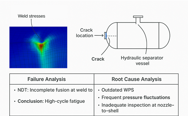
A hydrogen separator vessel in a petrochemical plant developed a longitudinal crack at a nozzle-to-shell junction after just 18 months in service, far below its expected design life.
Failure Analysis Outcome:
NDT (radiography + dye penetrant) revealed incomplete fusion at the weld toe. SEM images showed fatigue striations, confirming high-cycle fatigue as the mechanism. Finite Element Analysis (FEA) revealed localized stress intensification resulting from geometric discontinuities.
Conclusion: The vessel failed due to high local stresses under cyclic internal pressure.
Root Cause Analysis Findings:
Using the Fault Tree and Fishbone methods, RCA traced the issue beyond metallurgy. The fabrication records indicated that the Welding Procedure Specification (WPS) was outdated and lacked control over post-weld heat treatment. Additionally, operational logs indicated frequent pressure fluctuations during startup and shutdown cycles.
Root Causes Identified:
- Poor weld qualification procedure (technical).
- Process transient management gaps (systemic).
- Inadequate inspection coverage at nozzle-to-shell regions (procedural).
Outcome: The engineering team implemented revised WPS, startup sequence control, and critical weld zone monitoring. The same vessel design was safely reused after modification, avoiding a $45k USD replacement cost and 14 days of downtime.
Case 2: Centrifugal Pump Bearing Seizure - Rotating Equipment
A feedwater pump in a power plant experienced bearing seizure twice within six months, despite replacing the bearings with OEM parts each time.
Failure Analysis Outcome:
The disassembled bearing showed heavy surface scoring, discoloration, and pitting, indicating lubricant contamination. Oil sample analysis detected silica particles. Vibration trend data revealed progressive misalignment post-maintenance.
Conclusion: The bearing failed due to lubricant contamination and secondary misalignment.
Root Cause Analysis Findings:
RCA revealed that the contamination originated from improper oil filtration and open storage of lubricant drums near a grinding bay. The repeated misalignment was traced to a lack of laser alignment tools and the absence of technician training.
Root Causes Identified:
- No oil filtration unit or maintenance SOP.
- Poor housekeeping in the maintenance area.
- Human error due to inadequate training and supervision.
Outcome: Plant installed a 10-micron offline filtration system, revised maintenance procedures, and introduced technician certification for rotating alignment. Bearing failures dropped to zero in the next two years.

Case 3: Heat Exchanger Tube Rupture - Thermal-Mechanical Coupling
A shell-and-tube exchanger in an LNG terminal suffered a sudden tube rupture during startup.
Failure Analysis Outcome:
The metallurgical cross-section revealed creep embrittlement and oxidation, indicating prolonged overheating. Thermocouple data confirmed high shell-side temperature differentials.
Conclusion: Tube failure due to thermal fatigue from uneven temperature ramp-up.
Root Cause Analysis Findings:
RCA found missing startup temperature control interlocks and an improperly tuned PID loop in the Distributed Control System (DCS). Human factors analysis also revealed that the control operator bypassed ramp-up logic to meet production targets.
Root Causes Identified:
- Poor control system tuning
- Bypassed interlock
- Lack of automated ramp-up verification
Outcome: The RCA recommendations led to the redesign of the interlock, validation of control logic, and operator training. The changes were integrated into site-wide commissioning procedures.
Conclusion: Integrating RCA and Failure Analysis for Long-Term Reliability
When an equipment failure occurs, identifying what broke is only half the story. The accurate measure of engineering excellence lies in understanding why it broke and ensuring it never happens again. That’s where Failure Analysis (FA) and Root Cause Analysis (RCA) converge into a unified reliability strategy.
Failure Analysis delivers precision at the component level, metallurgical evidence, fracture morphology, stress data, and damage quantification. It provides engineers with the factual clarity needed to justify repair, rerating, or replacement decisions in accordance with API 579-1/ASME FFS-1. RCA, on the other hand, transforms those findings into system-level insight. It uncovers hidden process issues, procedural gaps, and human errors that often escape detection in purely technical investigations.
In high-integrity environments, such as refineries, LNG terminals, or power plants, combining both ensures that lessons learned from a single failure are applied across the entire asset base. Integrating FA and RCA within a structured mechanical integrity framework, supported by API RP 585 for incident investigation and ISO 14224 for data management, creates a continuous feedback loop for reliability improvement.
When done right, this approach turns every failure into a learning event, every report into a design improvement, and every RCA into a cost-saving opportunity. Instead of a find-and-fix culture, organizations evolve toward a predict-and-prevent reliability model, where engineers make decisions not just to restore function but to elevate performance.
Written By

PANDHARINATH SANAP
CEO and Co-Founder | IntPE
Pandharinath Sanap is the CEO and Co-Founder of Ideametrics, with more than 15 years of experience in mechanical engineering, engineering assessments, and technical reviews across industrial projects. He is an International Professional Engineer (IntPE)… Know more