Finite element analysis (FEA) in failure investigation is a simulation method used to reconstruct stress, strain, and deformation in failed components under real operating loads. Unlike visual inspection alone, simulation-based failure analysis helps engineers quantify stress concentrations, evaluate crack-driving forces, and validate root-cause hypotheses with physics-based evidence.
When a mechanical component breaks, cracks, or fails unexpectedly, the instinctive first step for most engineers is a careful visual examination of the damaged part. Visual inspection is fast, inexpensive, and often reveals important surface-level clues, fracture surface morphology, corrosion zones, deformation patterns, and the location of the initial crack. However, in the modern engineering failure investigation process, visual inspection alone is rarely sufficient to determine the true root cause of failure.
Hidden stress concentrations, complex load histories, subsurface material defects, and multi-physics interactions all contribute to component failures in ways that the human eye simply cannot detect or quantify. This is precisely where simulation and specifically finite element analysis (FEA) transforms the investigation from educated observation into rigorous computational science.
Engineering failure investigation is the systematic process of examining a failed component, structure, or system to determine the mechanism of failure, identify its root cause, and recommend corrective actions that prevent recurrence.
This article explains how simulation-based failure analysis and finite element analysis (FEA) in failure investigation extend far beyond what visual examination can reveal, providing engineers with the quantitative, physics-based insights needed to make accurate diagnoses and defensible engineering conclusions.
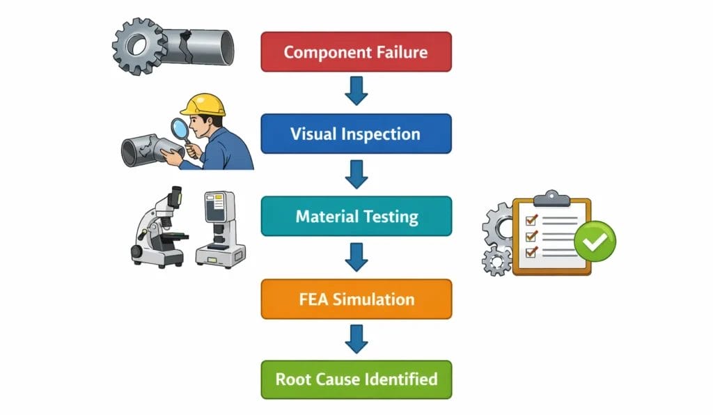
Figure 1: Overview of the engineering failure investigation process combining inspection, testing, and simulation.
What Is Failure Analysis in Engineering?
Engineering failure analysis is a structured discipline within mechanical and materials engineering that applies scientific principles to diagnose why a component or system ceased to perform its intended function. It draws on materials science, fracture mechanics, stress analysis, tribology, corrosion engineering, and increasingly, computational simulation.
Goals of Failure Investigations
- Identify the failure mechanism (fatigue, fracture, corrosion, wear, overload, creep)
- Determine the root cause (design flaw, material defect, manufacturing error, overloading, improper maintenance)
- Reconstruct the sequence of events that led to failure
- Provide evidence for litigation, insurance, or regulatory compliance purposes
- Develop corrective actions and design improvements to prevent recurrence
Industries That Rely on Failure Investigations
- Oil and gas (pipelines, pressure vessels, wellhead equipment)
- Power generation (turbine blades, boiler tubes, reactor components)
- Aerospace (structural airframe components, engine hardware)
- Automotive and heavy transportation (drive shafts, suspension, axles)
- Civil and structural engineering (bridges, cranes, offshore structures)
- Chemical and pharmaceutical processing (reactors, heat exchangers)
Common Failure Types Encountered in Practice
- Fatigue failure (cyclic loading causing crack initiation and propagation)
- Brittle fracture (sudden fracture with minimal plastic deformation)
- Ductile overload (excessive loading beyond material yield or ultimate strength)
- Stress corrosion cracking (combined action of tensile stress and corrosive environment)
- Creep failure (time-dependent deformation at elevated temperatures)
- Wear and erosion (surface degradation from mechanical contact or abrasive particles)
- Hydrogen embrittlement (loss of ductility due to hydrogen absorption)
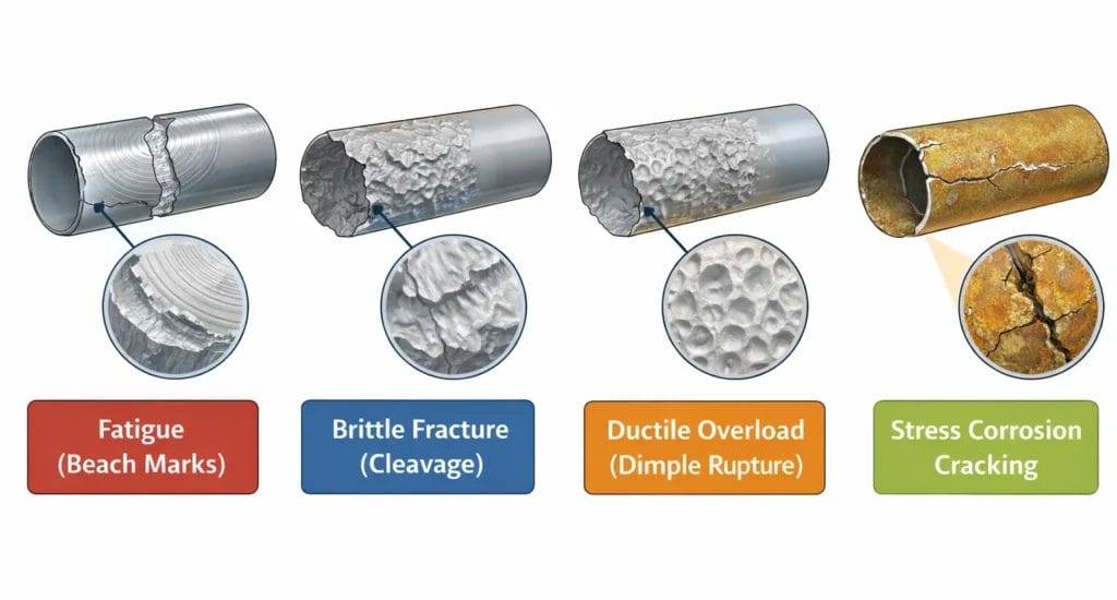
Figure 2: Typical fracture surface characteristics observed in engineering failure analysis.
Limitations of Visual Inspection in Failure Investigations
Visual inspection, including macroscopic examination with the naked eye and low-magnification optical tools, and microscopic examination via scanning electron microscopy (SEM), provides essential qualitative information. Investigators can identify fracture origins, ratchet marks indicating fatigue, beach marks from cyclic crack growth, oxidation zones, and evidence of impact damage.
However, visual examination has fundamental limitations that make it insufficient as a standalone root cause analysis tool:
1. Cannot Quantify Stress States
Visual inspection can show where a crack started, but it cannot tell you what the local stress magnitude was at that point, nor whether it exceeded the material’s fatigue or fracture threshold. Without quantified stress data, conclusions about root cause remain speculative.
2. Cannot Reconstruct Load History
Many failures result from transient load events a pressure spike, an unexpected vibration resonance, or a thermal shock that occurred before the failure and left no visible trace on the component. Simulation is required to reconstruct these load histories.
3. Cannot Detect Internal or Subsurface Defects in Context
While non-destructive testing (NDT) methods such as ultrasonic testing and radiography can detect subsurface flaws, visual examination alone cannot assess the criticality of those flaws under specific operating stresses. FEA in failure analysis allows engineers to model how a detected defect propagates under realistic loading.
4. Cannot Evaluate Design-Level Contributors
A fatigue failure at a shaft shoulder might result from a stress concentration factor that was not properly accounted for in the original design. Visual inspection shows the crack location simulation reveals whether the geometric design itself was the root cause by calculating the actual stress concentration factor under real operating loads.
Real-World Example:
Pressure vessel nozzle cracks: Visual inspection identifies the crack location, but FEA quantifies the thermal gradient and pressure-induced hoop stress that initiated the crack at the nozzle-to-shell junction. Rotating shaft failures: Beach marks visible under SEM confirm fatigue, but only stress analysis and load reconstruction reveal whether the cyclic bending stress exceeded the endurance limit at the identified fatigue origin. Pipeline failures: Visual examination shows corrosion pitting, but simulation-based failure analysis calculates whether remaining wall thickness under operating pressure would trigger fracture propagation.
Visual Inspection vs Simulation in Failure Analysis
Visual inspection identifies visible evidence such as crack origin, corrosion, deformation, and fracture appearance. Simulation-based failure analysis goes further by calculating stress fields, reconstructing load conditions, and testing whether a proposed root cause is mechanically plausible. In practice, visual inspection shows what failed, while FEA helps explain why it failed.
What Is Simulation-Based Failure Analysis?
Definition
Simulation-based failure analysis is the use of computational engineering methods primarily finite element analysis (FEA), computational fluid dynamics (CFD), and fracture mechanics modeling to mathematically reconstruct the stress, strain, thermal, and dynamic conditions that existed in a component at and before the moment of failure.
Rather than relying solely on physical evidence from the failed component, simulation-based failure analysis allows the investigator to recreate the failure event in a controlled computational environment, test multiple failure hypotheses, and quantitatively confirm or eliminate proposed root causes.
How Computational Methods Reconstruct Failure Events
- Geometric modelling of the failed component (including as-found dimensions, defects, and damage)
- Application of reconstructed operating loads (pressures, temperatures, speeds, forces)
- Material property assignment based on metallurgical testing results
- Calculation of stress, strain, and deformation distributions
- Comparison of computed stresses against failure criteria (yield strength, fracture toughness, fatigue limits)
Engineering Simulation Tools Commonly Used
- Finite element analysis (FEA) ANSYS, Abaqus, NASTRAN, SolidWorks Simulation
- Fracture mechanics simulation FRANC3D, Zencrack, NASGRO
- Computational fluid dynamics (CFD) for erosion, cavitation, flow-induced vibration
- Multibody dynamics for rotating machinery and drivetrain failures
What Is Finite Element Analysis (FEA)? A Beginner-Friendly Explanation
Finite element analysis (FEA) is a numerical computational method used to predict how a physical component responds to applied forces, pressures, temperatures, and other boundary conditions. It is the most widely used engineering simulation tool in modern structural and mechanical engineering.
The Mesh Concept
The foundation of FEA is the discretization of a continuous structure into thousands — or millions — of small, simple geometric shapes called elements (typically triangles or tetrahedra in 3D). These elements are connected at points called nodes, forming what is called the mesh. By dividing the complex geometry into small, manageable pieces, the governing equations of mechanics (the equilibrium equations, strain-displacement relationships, and constitutive laws) can be solved numerically at each node.
Think of it this way: Rather than solving one impossibly complex equation for the entire turbine blade or pressure vessel, FEA solves thousands of simpler equations for each small element, then assembles the results into a complete picture of the component’s behavior.
Boundary Conditions
Boundary conditions define how the component is constrained and loaded in the simulation. They include: fixed supports (where the component is bolted or welded), applied forces or pressures, temperatures, contact interactions with adjacent parts, and rotational constraints. The accuracy of FEA results is directly dependent on how accurately these boundary conditions reflect real operating conditions.
Stress and Strain Calculation
Once the mesh is defined and boundary conditions are applied, FEA software solves for the displacement field, how much each node moves under the applied loading. From displacements, the software calculates strains (deformation per unit length) and then stresses (internal forces per unit area) using the material’s constitutive relationship (for metals, typically Hooke’s Law in the elastic range, or elastoplastic models for yielding scenarios). These stresses are what investigators compare against material strength properties to identify failure zones.
How FEA Strengthens Failure Investigations: Four Critical Capabilities
A. Stress Concentration Detection
Stress concentrations occur at geometric discontinuities, holes, keyways, fillets, notches, thread roots, and weld toes. These are the locations where local stresses can be two to five times higher than the nominal stress calculated by simple beam or pressure vessel formulas. FEA in failure investigation allows analysts to compute the precise stress concentration factor (Kt) at any geometric feature and compare it directly to the location where fracture initiated.
In practice, FEA often confirms that a component failed at a location where visual inspection showed nothing unusual but where the computed stress concentration factor was critically high given the applied cyclic loading. This is a conclusion that visual inspection alone could never reach.
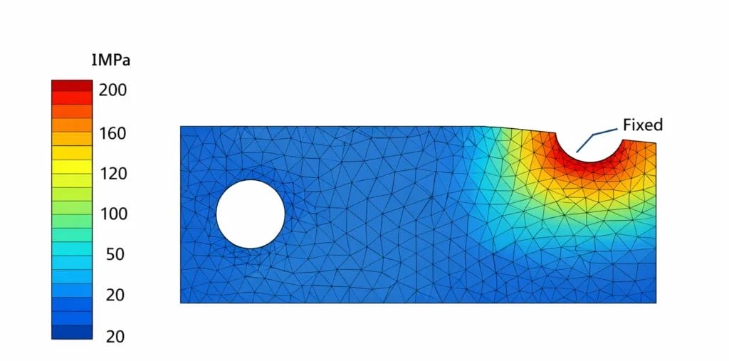
Figure 3: FEA stress contour showing stress concentration near a geometric discontinuity.
B. Crack Propagation Analysis
Once a crack initiates, the rate at which it propagates through a material depends on the stress intensity factor (K) at the crack tip, which is a function of crack size, crack geometry, and the applied stress field. Fracture mechanics-based FEA enables investigators to simulate crack growth under cyclic or sustained loading, estimating how many load cycles were required for the crack to grow from its detected size to the critical size at which fast fracture occurred.
This capability is particularly valuable for fatigue failure investigations, where the number of cycles to failure provides crucial evidence about whether the component operated within its design life or was subjected to loading beyond its original specification.
C. Load Reconstruction
When exact operating loads at the time of failure are unknown which is frequently the case, simulation-based failure analysis allows investigators to work backward. By applying different load magnitudes to the model and comparing the resulting deformation patterns and fracture characteristics to the actual failed component, analysts can narrow down the probable load range at failure. This technique, sometimes called inverse analysis, is a powerful differentiator between simulation-based failure analysis and traditional visual-only investigations.
D. Validation of Failure Hypotheses
Perhaps the most important function of FEA in failure analysis is hypothesis testing. When multiple potential root causes are under consideration for example, overloading versus material deficiency versus geometric design error each hypothesis can be coded into a separate simulation scenario. The scenario that produces computed stresses consistent with the observed fracture location, morphology, and load level is the one that most likely represents the actual failure mechanism. This transforms root cause analysis from opinion-based reasoning into evidence-based engineering science.
Step-by-Step Failure Investigation Workflow Using Simulation
A rigorous simulation-enhanced failure investigation follows a structured sequence:
- Evidence Preservation: Photograph and document the failed component in-situ before any disturbance. Record operating data logs, maintenance history, and ambient conditions at the time of failure. Preserve fracture surfaces by preventing further oxidation or damage.
- Visual and Macroscopic Inspection: Examine the failed component under ambient and low-power magnification. Identify fracture origin locations, fracture surface features (beach marks, chevron marks, shear lips), material anomalies, corrosion, and evidence of previous repairs.
- Metallurgical and Material Testing: Conduct chemical composition analysis, hardness testing, tensile and impact testing, and scanning electron microscopy (SEM) fractography. Compare results against material specifications to determine whether material quality contributed to failure.
- Load and Operating Condition Analysis: Review design calculations, operating pressure records, speed logs, temperature data, and maintenance records. Establish the range of loads the component was likely subjected to during its service life.
- Finite Element Simulation: Build or reconstruct the geometry of the component in CAD software. Create the FEA mesh, apply material properties from testing, and apply reconstructed boundary conditions and loading. Run stress analysis simulations and, if applicable, fracture mechanics crack propagation analyses.
- Root Cause Identification and Reporting: Compare FEA results (stress fields, crack driving forces, deformation patterns) with physical evidence from the failed component. Identify the primary root cause and any contributing factors. Document findings in a formal failure investigation report with supporting evidence from both physical examination and simulation.
Case Study: Fatigue Failure in a Centrifugal Pump Drive Shaft
Consider a centrifugal pump drive shaft in a petrochemical plant that fractured after 14 months of service, well below its 10-year design life. The failure resulted in an unexpected production shutdown and an investigation was initiated.
Visual Inspection Findings
- Fracture surface showed characteristic beach marks, confirming fatigue failure mechanism
- Fracture origin identified at the shaft shoulder (step-down in diameter) where a seal ring was seated
- No visible corrosion, surface pitting, or external damage at the origin site
- Hardness and chemical composition testing confirmed the shaft material met specification
What Visual Inspection Could Not Answer
Visual inspection confirmed fatigue as the mechanism but could not explain why the shaft failed at only 14 months when designed for 10 years. The possible root causes included: (1) the shaft shoulder fillet radius being undersized (increasing stress concentration), (2) operating torque being higher than the design specification, or (3) a resonant vibration condition at a critical speed.
Simulation Results (FEA in Failure Analysis)
The engineering team built a 3D FEA model of the shaft including the precise shoulder geometry. Material properties from testing were applied. Three simulation scenarios were run:
- Scenario A: Design load with as-specified fillet radius (r = 5 mm) – computed stress at shoulder = 72 MPa, well below the endurance limit of 210 MPa
- Scenario B: Design load with as-found (measured) fillet radius (r = 1.8 mm) – computed stress at shoulder = 198 MPa, approaching but not exceeding the endurance limit
- Scenario C: Design load with as-found fillet radius AND 40% torque overload condition (confirmed from pump performance records) – computed stress = 287 MPa, exceeding the endurance limit and consistent with 14-month failure
Root Cause Conclusion
Simulation-Confirmed Root Cause
The fatigue failure resulted from the combination of an undersized fillet radius at the shaft shoulder (manufacturing deficiency Kt elevated from 1.6 to 3.1) and sustained torque overload due to process fluid viscosity exceeding the pump’s original design specification. Neither factor alone was sufficient to cause premature failure. Simulation was essential to quantify both contributors and confirm the combined effect.

Figure 4: FEA stress distribution showing high stress concentration at the shaft shoulder where fatigue initiated.
Simulation vs Visual Inspection: Key Differences
| Attribute | Visual Inspection | Simulation-Based Analysis (FEA) |
|---|---|---|
| Nature of Output | Qualitative observations | Quantitative stress, strain, deformation data |
| Root Cause Certainty | Inferred / presumed | Mathematically validated |
| Stress Quantification | Cannot quantify | Precise stress fields at every location |
| Subsurface Analysis | Limited to NDT findings | Models subsurface cracks and defect growth |
| Load History Reconstruction | Not possible | Inverse analysis and scenario simulation |
| Cost | Low to moderate | Moderate to high (software, skilled analysts) |
| Time Required | Hours to days | Days to weeks for complex components |
| Hypothesis Testing | Based on experience/intuition | Multiple scenarios tested computationally |
| Admissibility in Litigation | Accepted, limited in scope | High – defensible, quantified evidence |
| Identifies Design Flaws | Rarely | Consistently and quantitatively |
Industries Where Simulation-Based Failure Analysis Is Critical
Oil & Gas
Pipeline crack assessments, pressure vessel fitness-for-service evaluations, and riser fatigue analyses in offshore environments all depend on simulation-based failure analysis. Regulatory standards such as API 579 and DNV-RP-C203 explicitly incorporate fracture mechanics and FEA-based assessment methods.
Power Generation
Steam turbine blade failures, boiler tube cracking, and nuclear reactor component assessments involve complex thermal, mechanical, and cyclic loading interactions that require finite element analysis failure investigation methods. The consequences of failure in power plants are severe enough that simulation is considered mandatory in most jurisdictions.
Aerospace
Aerospace certification (FAA, EASA) requires rigorous demonstration of structural integrity, including damage tolerance analysis using fracture mechanics. FEA in failure analysis is the standard tool for investigating in-service incidents involving cracks in aircraft structures, engine casings, and landing gear components.
Automotive and Heavy Manufacturing
Recall investigations, warranty failure analyses, and product liability cases in the automotive sector rely heavily on simulation to reconstruct crash events, component overload scenarios, and long-term fatigue failures in powertrain and suspension components.
Chemical and Pharmaceutical Processing
Heat exchanger tube failures, reactor vessel cracking, and agitator shaft fatigue failures in process industries are routinely investigated using simulation-based failure analysis, particularly where aggressive chemical environments interact with mechanical stress in stress corrosion cracking scenarios.
The Future of Failure Investigations: Digital Twins, AI, and Predictive Analysis
Digital Twins
A digital twin is a continuously updated virtual replica of a physical asset, populated with real-time sensor data from the operating equipment. In the context of failure analysis, digital twins enable investigators to access a full computational record of the component’s loading history — eliminating the guesswork of load reconstruction that is currently one of the most challenging aspects of post-failure simulation.
AI-Assisted Simulation
Machine learning models are being developed to accelerate finite element analysis by predicting stress fields from geometric and loading parameters, reducing simulation time from hours to seconds. In failure investigations, AI-assisted simulation will enable faster screening of multiple failure hypotheses, making simulation accessible even in time-sensitive forensic engineering contexts.
Predictive Failure Analysis
The ultimate evolution of simulation-based failure analysis is shifting from reactive investigation (after failure) to proactive prediction (before failure). By integrating FEA-based fracture mechanics models with real-time operational data and statistical degradation models, engineers can predict when a component is approaching critical crack size enabling planned maintenance before a catastrophic failure event occurs.
Conclusion: Simulation Is No Longer Optional in Failure Investigations
The engineering failure investigation process has evolved far beyond what visual examination alone can support. While visual inspection remains an essential first step, identifying fracture mechanisms, corrosion patterns, and physical damage, it is inherently limited in its ability to quantify stresses, reconstruct load histories, model crack propagation, and test competing root cause hypotheses.
Simulation-based failure analysis, and specifically finite element analysis (FEA) in failure investigation, provides the quantitative, physics-based rigor that modern engineering investigations demand. Whether the goal is determining root cause for corrective action, providing defensible evidence in litigation, satisfying regulatory requirements, or improving future designs, simulation transforms failure analysis from observation into science.
For engineers, reliability professionals, and investigators working in high-consequence industries, oil and gas, power generation, aerospace, automotive, and heavy manufacturing, mastering and deploying simulation-based failure analysis is no longer an advanced specialization. It is a core professional competency for anyone serious about understanding why things fail and preventing them from failing again.
Frequently Asked Questions (FAQ)
Finite element analysis (FEA) in failure investigation is the application of numerical simulation to reconstruct the stress, strain, and deformation conditions that existed in a failed component under its operating loads. By dividing the component geometry into thousands of small elements and solving the governing equations of mechanics at each node, FEA provides quantitative stress distributions that allow investigators to determine whether and where stresses exceeded material strength limits, enabling mathematically defensible root cause identification.
Simulation is important in failure analysis because visual inspection alone cannot quantify stress states, reconstruct load histories, model crack propagation rates, or test multiple failure hypotheses. Simulation-based failure analysis allows investigators to mathematically confirm root causes by reproducing the failure conditions in a controlled computational environment, producing quantitative evidence that supports corrective design actions and is defensible in regulatory and legal contexts.
Visual inspection can identify the failure mechanism (such as fatigue, overload, or corrosion) and the location of failure initiation, but it generally cannot identify the root cause on its own. Root cause determination requires understanding the stress state, load history, and material response at the failure site, information that requires computational simulation, particularly finite element analysis, combined with metallurgical testing to produce a reliable, defensible conclusion.
FEA helps identify stress concentrations by computing the full stress field across a component’s geometry under applied loads, including at geometric discontinuities such as notches, holes, fillets, keyways, and weld toes. The computed stress concentration factor (Kt) at the failure origin can be compared against the material’s fatigue or fracture properties to determine whether the geometric stress amplification was sufficient to initiate and propagate the observed failure a determination that visual inspection cannot make quantitatively.
Written By

PANDHARINATH SANAP
CEO and Co-Founder | IntPE
Pandharinath Sanap is the CEO and Co-Founder of Ideametrics, with more than 15 years of experience in mechanical engineering, engineering assessments, and technical reviews across industrial projects. He is an International Professional Engineer (IntPE)… Know more